Installation Guide MX1 Fire Alarm System (NZ)
LT0360 ISSUE 2.43 29 NOVEMBER 2017 PAGE 22
Note: When using fibre cabling you must allow for cable entry and minimum bend radius in deciding the fibre cable
route to the switch (commonly 60-90mm for field cables, 40mm for patch leads).
AS1668 Fire Fan Controls
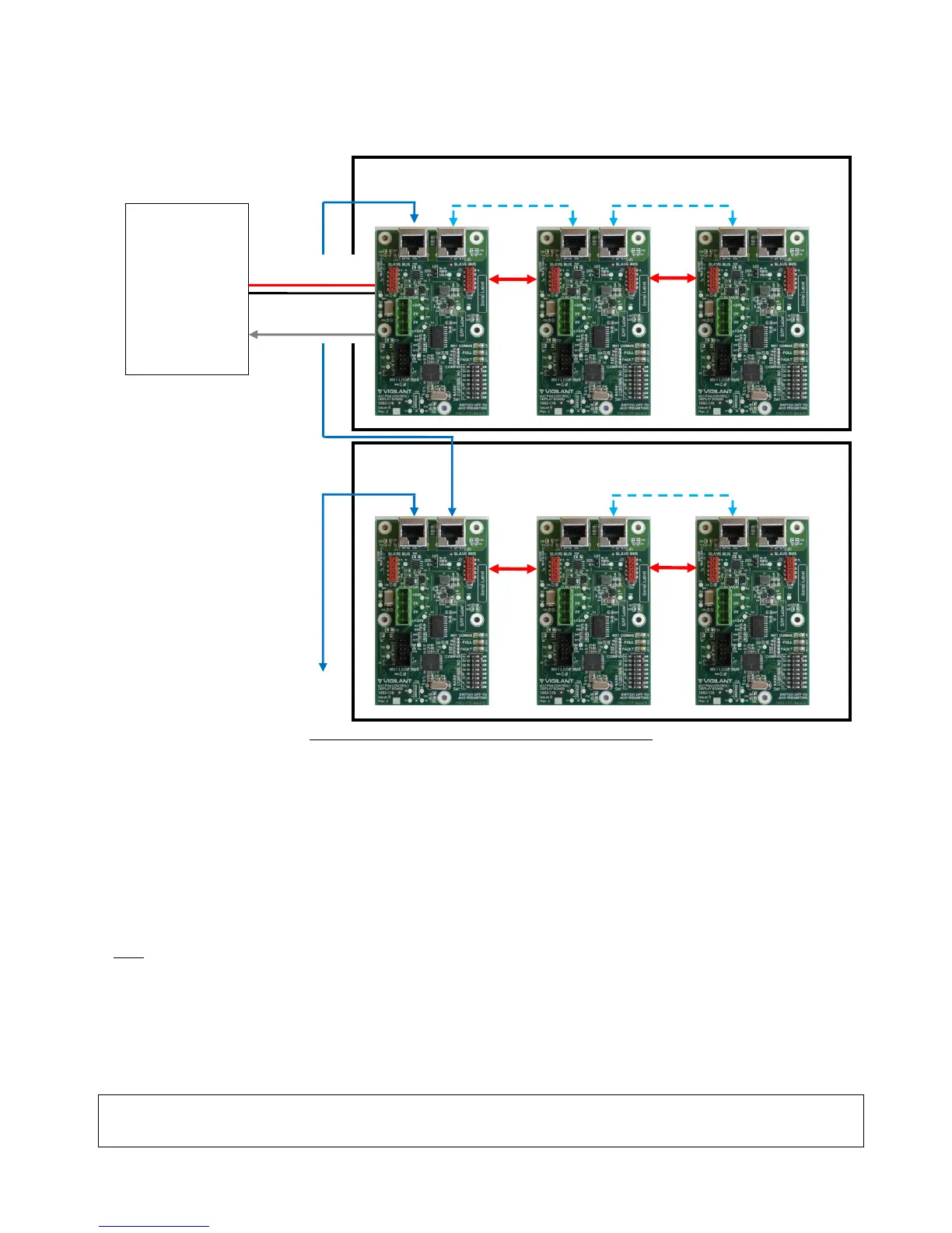
Figure 36 – MX1 Fan Control Boards Wiring Diagram
AS1668 fan controls are mounted in MX1 15U panels by using MX1 AS1668 3U 19” rack doors (FP1056) that come
with 2 fan controls fitted. Each door can accommodate 12 controls in total by the addition of five FP1057 Fan
Controls Expansion Kits. Each kit provides 2 fan controls. The MX1 panel can support up to 126 fan controls (63
boards), although additional cabinets will be required for more than 36 controls in a 15U cabinet.
Installation of the MX1 Fan Controls is detailed in the MX1 Fan Controls Install Instructions (LT0587). A copy of
LT0587 is included with every FP1056 MX1 Fan Controls 3U 19” rack door and FP1057 MX1 Fan Controls
expansion kit.
A generalized wiring arrangement is shown in Figure 36.
Note:
The DIP switch on each fan control needs to be set to a unique odd number from 1 to 125. All controls must have
their ‘M’ switch set to ON except the one that connects to the MX1 Controller or MX Loop Card serial port, which
has its ‘M’ switch set to OFF.
INITIAL POWER ON
The MX1 is shipped with a factory default configuration loaded.
WARNING: Do not connect the battery when first powering up. Use the mains power supply alone to start with,
so that the current into any wiring faults will be limited to a reasonably safe level.