EasyManua.ls Logo

Vigilant MX1 - Addressable Loop Wiring

Vigilant MX1
26 pages
Print Icon
To Next Page IconTo Next Page
To Previous Page IconTo Previous Page
Loading...
Installation Guide MX1 Fire Alarm System (NZ)
LT0360 ISSUE 2.43 29 NOVEMBER 2017 PAGE 6
Addressable Loop Wiring
Figure 6 shows the
general form of the
addressable loop wiring
from the MX1.
The screw terminals on
the controller board can
accommodate loop wire
of up to 4.0mm
2
in size.
Correct polarity must be
maintained around the
loop as most MX
devices are polarity
sensitive.
NZS 4512:2010
requires that short
circuit isolators (isolator
base, isolator module,
or in-built to
module/detector) be
located at zone
boundaries to restrict
the effect of short
circuits or overloads to a
single zone.
F
IR
E
D
E
F
N
C
2
C
2
N
O
2
MX1 CONTROLLER
N
C
2
C
2
N
O
2
AR-
BRIGADE SIGNALLING
INTERFACE
ASE+
0V
ASE
INTERFACE
Detector
DetectorDetector
Detector
Detector
Detector Detector
Module
Module
Detector
AR+
AL-
AL+
Figure 6 Addressable Devices on MX Loop
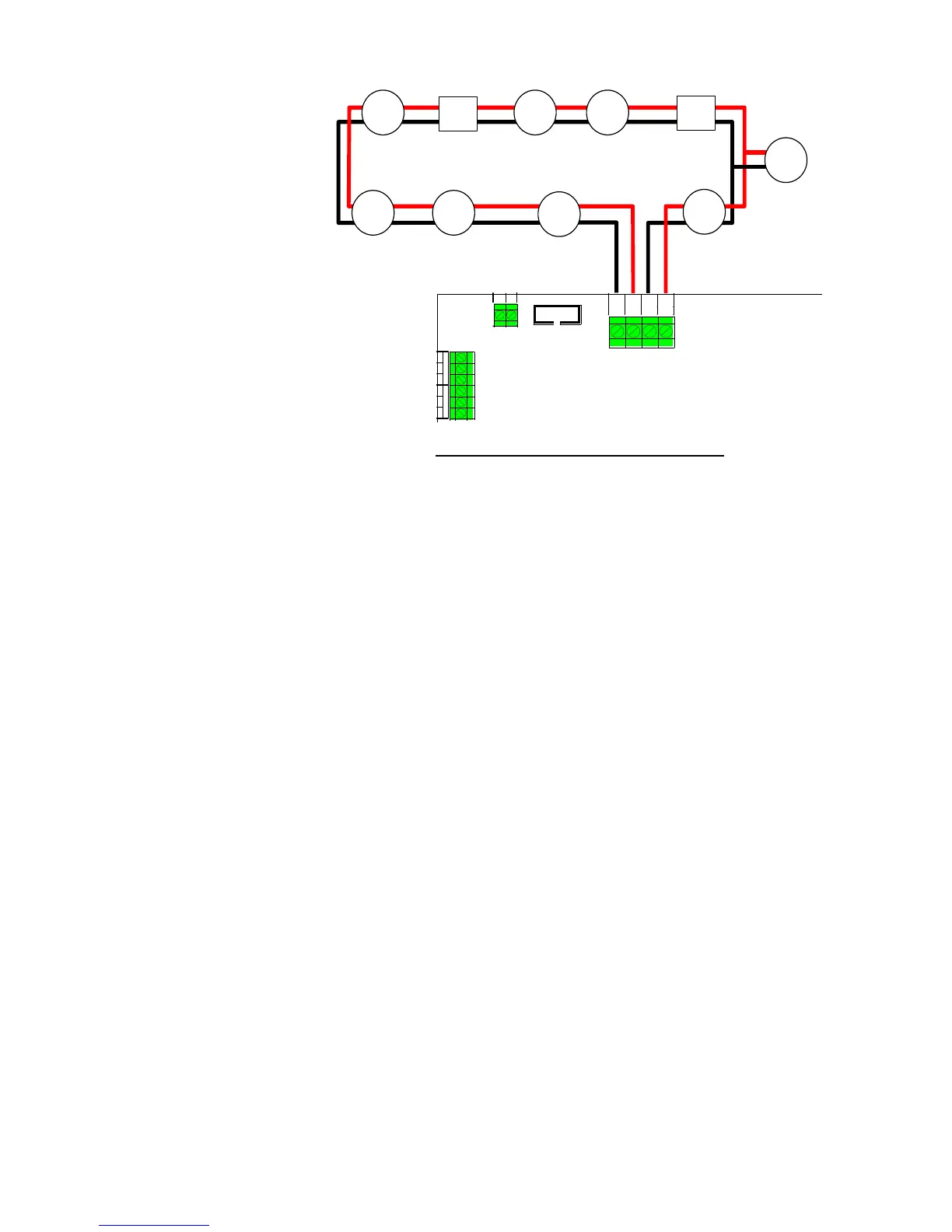
Note that the 850P, 850PH, 850PC and 850H detectors have built-in short circuit isolators when fitted to 4B-C
bases.
Refer to the MX1 System Design Manual (LT0361) for detailed information on acceptable current loads and wire
sizes for the addressable loop wiring.
A range of brackets is available for mounting certain MX modules in the MX1 15U Cabinet typically where the MX
Loop Cards mount. Refer to the relevant installation instructions LT0557 and LT0591 for details.

Other manuals for Vigilant MX1

Related product manuals