Installation Guide MX1 Fire Alarm System (NZ)
LT0360 ISSUE 2.43 29 NOVEMBER 2017 PAGE 11
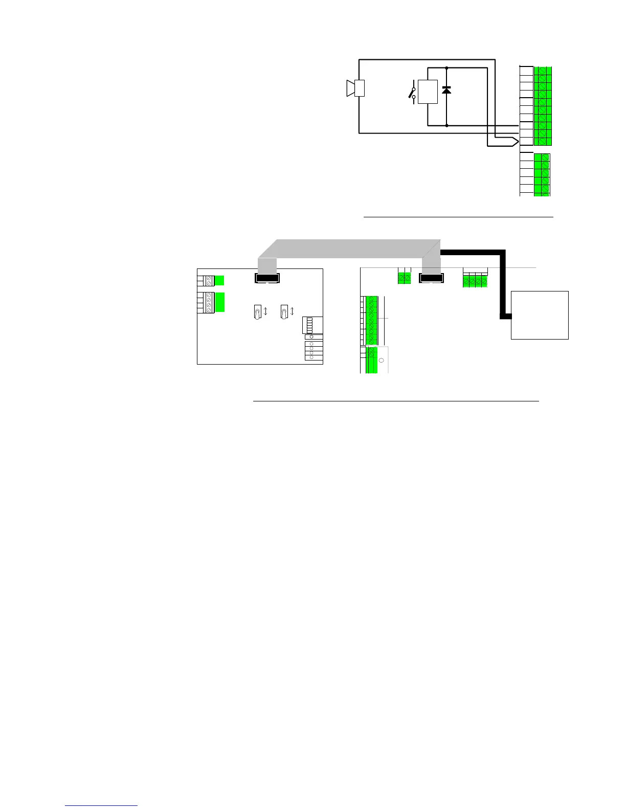
General Purpose Outputs (OUT1, OUT2)
MX1 has two protected open collector outputs which can be
used for driving small loads, e.g., external buzzers or relays.
Figure 14 shows examples of connection to a fault buzzer
and an external relay. The maximum load current is 500mA
for each output, i.e., 54 minimum load resistance. The
relay suppression diode can be any general purpose diode
such as 1N4004.
Each output can be configured for open circuit fault
detection if this is required.
The MX1 must be configured with user logic or a zone
mapping for these outputs to produce any effect. There is
no default action.
The gear plate has
plastic standoffs fitted to
mount a GP SGD, part
number PA0862, or GP
Brigade Relay Interface,
part number PA0861; in
the top left part of the
Slimline cabinet or on
the top of the right-hand
gear plate return of the
15U gear plate.
The PA0861 or PA0862
is connected to the
Brigade Signalling
Interface connector on
the Controller either by
an FRC loom, part
number LM0172,
supplied with the unit, or
a (longer) LM0084
supplied with the 15U
MX1.