T-GEN 50
Both the Slimline cabinet and 15U cabinet gear
plates are fitted with five plastic standoffs and one
metal standoff to mount a T-GEN 50 tone generator.
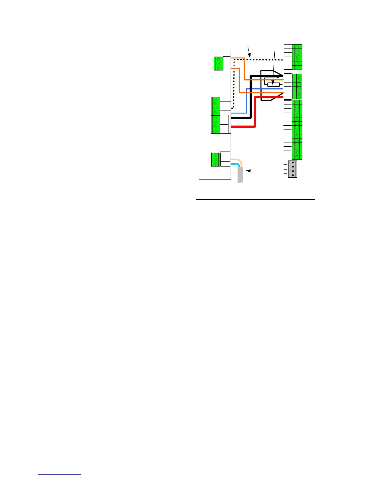
This can be connected to either of the ANC1 or
ANC2 relay outputs as shown in Figure 8.
A pre-made loom is available for this purpose, part
number LM0319, which will plug in directly to the 6
way header on ANC1. An LM0319 is supplied with
each MX1.
If the T-GEN 50 is fitted elsewhere, for example in a
separate FP0944 empty Slimline MX1 cabinet, then
an LM0401 (1.3m long) can be used or the LM0319
wiring can be extended.
This wiring provides complete supervision of wiring
open and short circuits, as well as passing the state
of the T-GEN 50’s fault relay to the MX1 controller.
The 10k resistor is critical to this supervision and
should not be omitted, or a different value
substituted.
When the T-GEN 50 Alert and Evacuation tones
must be separately controlled by the MX1, one of the
GP OUT terminals must be connected to the
T-GEN 50’s A/I/E- input, as shown. This is not
default operation, and the MX1 must be specially
configured.
Refer to the T-GEN 50 Installation Manual (LT0186)
for information about its DIP switch and link settings,
but the following settings are required at least:
Figure 8 – Wiring Ancillary Relay 1 to T-GEN 50
SW4 = ON, to enable Alarm Input supervision
SW5=OFF, for non-latching ALM
LK7 = RELAY, to enable the Fault Relay output
LK2 and LK6 = MASTER
The MX1 must be configured to have “contact” supervision
enabled for whichever of ANC1 or ANC2 relay is used.