Installation Guide MX1 Fire Alarm System (NZ)
LT0360 ISSUE 2.43 29 NOVEMBER 2017 PAGE 15
Ring Networking Using I-HUBs
For detailed information on mounting, wiring and programming of the I-HUB including use in other configurations
and network topologies please refer to the Panel-Link Intelligent I-HUB User’s Manual (LT0229).
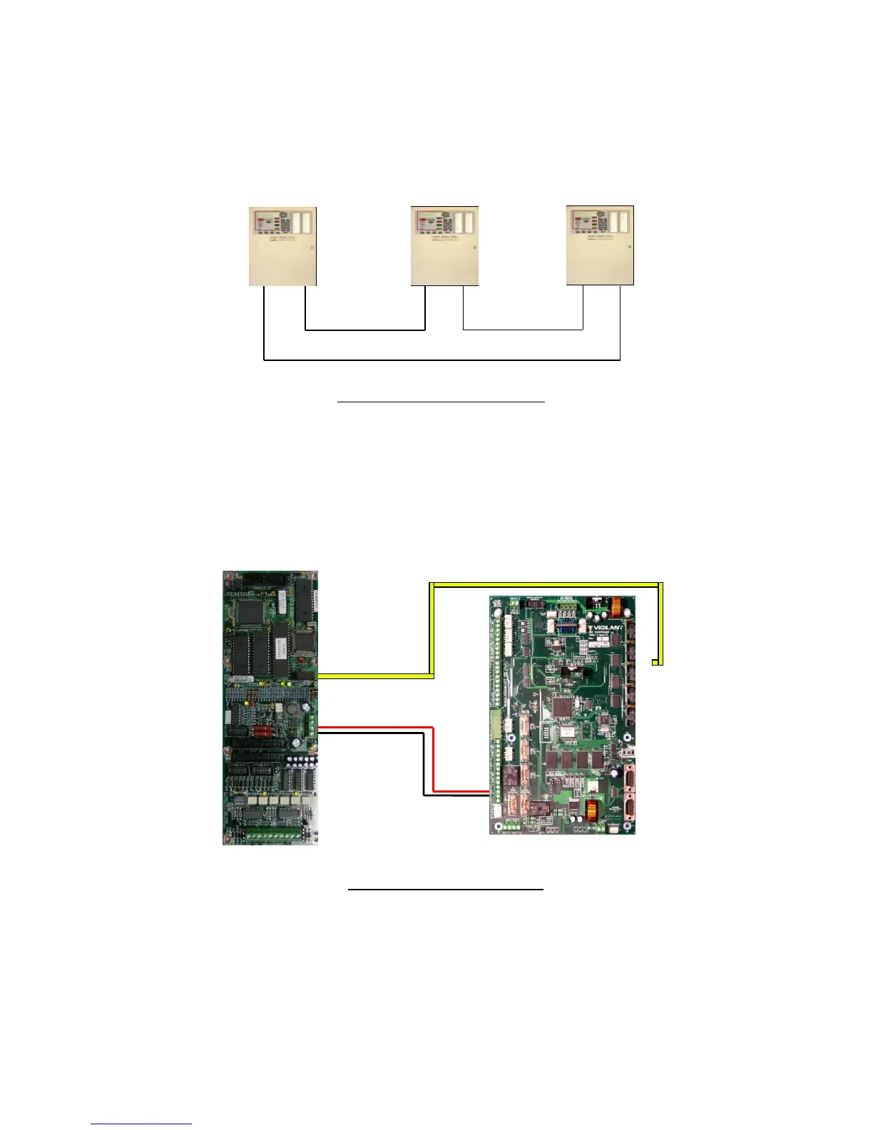
The I-HUB can be used in a number of different network configurations. It is recommended to use the “RING”
configuration shown in Figure 21. The I-HUB comes pre-configured for ring operation, with Port 5 (J4) connected to
the MX1 serial port configured for networking.
Figure 21 – Network Ring Example
I-HUB Wiring
The I-HUB is powered by one of the MX1’s +VBF supplies. This supply must not be used for any directly-connected
field wiring, to ensure that fuse failure caused by an external wiring fault does not disable the network. Alternatively,
the I-HUB (and fibre modems if included) could be powered off the Loop Interface Supply terminals J33 using a
fused power lead (e.g., a spare LM0459 supplied with an MX Loop Card). The I-HUB’s J4 TTL serial port is
connected using loom LM0152 to whichever serial port (0, 2, 3 or 4) is configured in the MX1 for networking as
shown in Figure 22.
Figure 22 – I-HUB to MX1 Wiring
I-HUB Copper Ring
The I-HUBs are typically connected in a ring configuration as shown in Figure 23.