VIKING TECHNICAL SUPPORT 1.800.908.0884
11
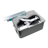
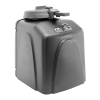
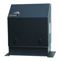
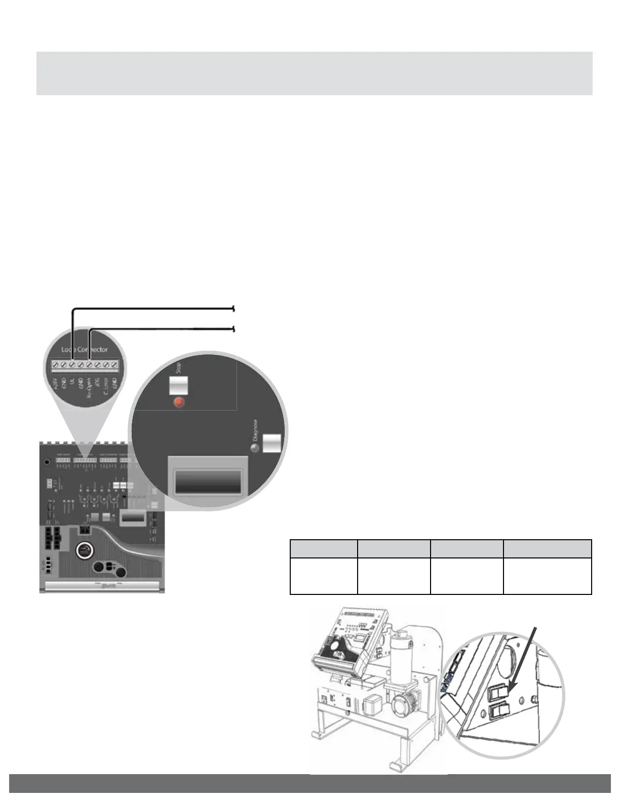
Manual Release
When manual operation is required:
1.
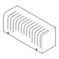
Remove the operator cover
2.
Press the Manual Release Switch
(top) to the “RELEASE” Position.
The gate can now be moved manually.
To resume normal operation, press
the switch to the “ENGAGE” position.
MANUAL RELEASE
SWITCH
“UL” Protects against entrapment in both the opening and closing directions. Input will
reverse the gate momentarily in the opposite direction it was traveling. Refer to page 28.
“Re-Open” Protects against entrapment in the closing direction ONLY. Input will reverse the
gate all the way to the Open Limit. Refer to page 29.
IMPORTANT SAFETY INFORMATION
! WARNING! Not Following these instructions may cause severe injury or death.
! Cable use in Class 2 circuit to an external device shall be type CL2, CL2P, CL2R, CL2X or other
cable with equivalent or better electrical, mechanical, and fl ammability ratings.
Monitored Entrapment Protection Installation
STEP 1:
Connect the monitored entrapment protection
sensor(s) to the Viking control board as illustrated.
! IMPORTANT: A minimum of two Monitored External Entrapment Sensors are required to be
connected as follows: One to the UL terminal and one connected to the Re-Open terminal,
OR two snesors connected to the UL terminal, one for EACH DIRECTION of travel.
UL LEARN
NO LEARN
10K Monitored Terminal
10K Monitored Terminal
STEP 2:
Execute the Learn Process:
•
Toggle the “Diagnose” button
until you see UL LEARN NO LEARN
on the LCD Display.
•
Press and hold the “Stop” button.
•
Toggle the “Diagnose” button
once.
•
The number of Monitored sensors
connected to the “UL” or Re-
Open terminals will now be
displayed.
EXAMPLE: UL LEARN
UL2 RO1
UL SENSOR ERRORS:
If an problem occurs with one of the monitored
entrapment sensors, the “Stop” LED will flash and
an ERR message will be displayed, indicating which
input terminal(s) the sensor is connected to.
TERMINAL: “UL” “Re-Open” “UL” & “Re-Open”
ERROR
MESSAGE:
ERR SENS
UL
ERR SENS
RO
ERR SENS
UL RO