0478 403 9800 H - EN
36
Folding out the transport chassis –
transport position:
● Raise transport chassis (1) slightly with
one hand and hold.
● Pull out retaining pin (2) and remove
locking pin (3).
● Fold transport chassis (1) downwards
to the stop.
● Insert locking pin (3) from the left or
right to the stop in the illustrated bore
and secure with retaining pin (2).
Folding in the transport chassis:
● Unload transport chassis (1) by raising
the machine.
● Pull out retaining pin (2) and remove
locking pin (3).
● Set the machine down on the brake
spur.
● Fold transport chassis (1) upwards and
hold.
● Insert locking pin (3) from the left or
right to the stop in the illustrated bore
and secure with retaining pin (2).
11.5 Adjusting the brake spur
By means of the brake spur, the
resistance and consequently the
speed of propulsion are regulated during
tilling. The brake spur can be adjusted for
better control.
Adjusting the brake spur:
● Folding out the transport chassis into
the transport position. (Ö 11.4)
Ensure that the machine is standing
stably and securely.
● Hold the brake spur (1) with one hand.
● Fold open the securing clip of folding
retainer (2) and remove the folding
retainer.
● Move brake spur (1) to the desired
position. The relevant bore in the brake
spur must align with the side bores (3)
in the adapter.
● Insert folding retainer (2) through the
bores and secure by folding up the
securing clip.
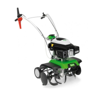
11.6 Starting the engine
Models HB 445 and HB 445 R are
equipped with a primer for cold
starting.
Models HB 560, HB 585 and HB 685
feature an automatic choke (Smart
Choke).
● Set the throttle lever to the start
position. (Ö 8.1)
● Only HB 445, HB 445 R:
if the engine is cold, press primer (1)
three times.
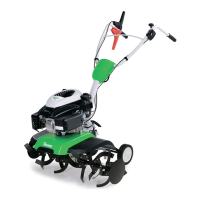
● Grasp the handle of the recoil starter
rope (2) firmly with one hand and hold.
● Slowly pull out the recoil starter rope (2)
to the point of compression resistance.
Then pull forcefully with one swift tug to
arm's length. Slowly return the recoil
starter rope (2) so that it is rolled up
again.
Repeat the procedure until the engine
starts.
11.7 Stopping the engine
● In order to stop the engine, move the
throttle lever to the Stop position.
(Ö 8.1)
The engine comes to a stop after a
short run-down time.
11.8 Engaging and disengaging self-
propulsion (forwards)
Engaging self-propulsion (forwards):
● Move the tiller to the area to be tilled
with the engine stopped. (Ö 13.)
● Start the engine. (Ö 11.6)
● Hold the tiller firmly at the handles with
both hands.
● Actuate and hold the black self-
propulsion lever (forwards). (Ö 8.2)
The drive shaft with the installed work
tools begins to rotate and the tiller
moves forwards.
Disengaging self-propulsion
(forwards):
● Release self-propulsion lever
(forwards). (Ö 8.2)
The drive shaft with the installed work
tools stops.
11.9 Engaging and disengaging self-
propulsion (reverse) (HB 445 R,
HB 560, HB 585, HB 685)
The HB 445 R, HB 560, HB 585 and
HB 685 tillers are equipped with a reverse
gear.
26
If the engine is warm, do not
actuate the primer.
Operating in very cold weather:
If necessary, actuate the primer
following a work break, as the
engine can cool down quickly.
27
Ташев-Галвинг ООД
www.tashev-galving.com
 Loading...