ENGLISH - 5
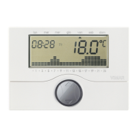
The time-programmable thermostat, when coupled with the Radio
Transceiver Base Station (figure 4.1), offers additional dedicated
function menus for the configuration of the system, which can be
accessed irrespective of the current thermostat operating mode.
Recognition of the Radio Base Station is signalled by the icon
.
The first time-programmable thermostat used for configuring the
system is identified as the Primary Thermostat (LOGICAL_ID 01).
All subsequent thermostats are iden-
tified as secondary thermo-
stats. For examples of
types of installations
see paragraph 10).
4. ADDITIONAL THERMOSTAT FUNCTIONS
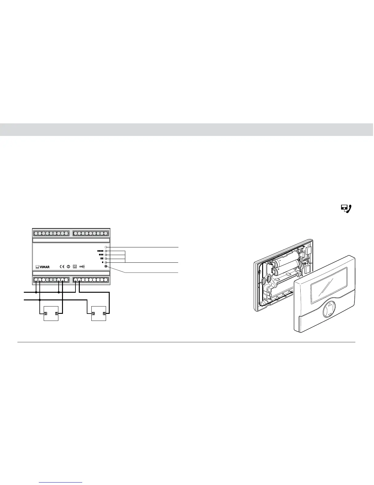
3.2 Radio relay actuator
The radio relay actuator is suitable for EN 50022 rail mount instal-
lation, occupies six 17.5 mm modules and must be installed as
shown in figure 3.2.1.
C
NO NC
C
NO
L
N NC
C
NO NC
C
NO NC
out 2out 1 out 3 out 4
01934 ATTUATORE RF 4 CANALI
SUPPLY:
230 V~
50-60 Hz
4 OUTPUTS:
1B
6(2) A 250 V~
ON
P
L
N
U1 U2
Power indicator LED
Relay channel status LED
Programming button P
Electrical connections for
controlling circulation pumps,
solenoid valves etc.