EasyManua.ls Logo

Vimar radioclima User Manual

Vimar radioclima
184 pages
Go to English
To Next Page IconTo Next Page
To Previous Page IconTo Previous Page
Page #9 background imageLoading...
Page #9 background image
ITALIANO - 5
Il cronotermostato, abbinato alla Base Radio Bidirezionale (figura
4.1), dispone di menù dedicati alla gestione di funzioni aggiuntive
necessarie per la configurazione del sistema, alle quali è possibile
accedere indipendentemente dalla modalità operativa in cui si trova
il cronotermostato. Il riconoscimento della Base Radio viene visua-
lizzato con l’icona
. Il primo cronotermostato utilizzato per la
configurazione del sistema viene iden-
tificato come Cronotermostato
Primario (ID_LOGICO 01).
Tutti i successivi cro-
notermostati vengo-
no riconosciuti come
secondari. Per gli
esempi sulle tipolo-
gie installative vedere
il paragrafo 10).
4. FUNZIONI AGGIUNTIVE DEL
CRONOTERMOSTATO
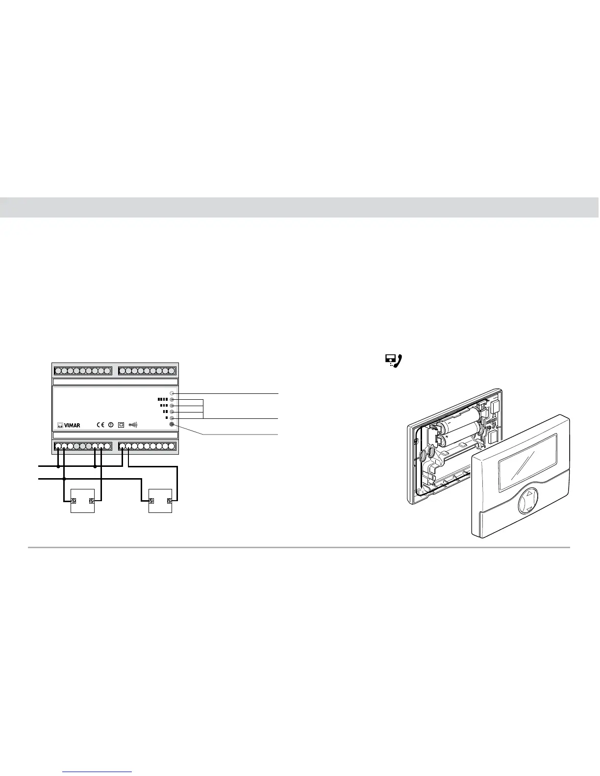
3.2 Attuatore radio a relè
L’attuatore radio a relè è adatto per essere installato su guida EN
50022, occupa 6 moduli da 17,5 mm e deve essere installato come
indicato in figura 3.2.1.
C
NO NC
C
NO
L
N NC
C
NO NC
C
NO NC
out 2out 1 out 3 out 4
01934 ATTUATORE RF 4 CANALI
SUPPLY:
230 V~
50-60 Hz
4 OUTPUTS:
1B
6(2) A 250 V~
ON
P
L
N
U1 U2
Led alimentazione
Led stato canali relè
Tasto P programmazione
Collegamenti elettrici per comando
di pompe di circolazione, elettro-
valvole, ecc.
Figura 3.2.1
Esempio di collegamento tra attuatore radio a relè e caldaia:
Fig. 3.2.1
Fig. 4.1

Table of Contents

Question and Answer IconNeed help?

Do you have a question about the Vimar radioclima and is the answer not in the manual?

Vimar radioclima Specifications

General IconGeneral
BrandVimar
Modelradioclima
CategoryThermostat
LanguageEnglish

Summary

3. INSTALLATION

3.1 Radio Transceiver Base Station

Details on wall-mounting the Radio Transceiver Base Station at a suitable height and distance from other components.

3.2 Radio relay actuator

Information on installing the radio relay actuator for EN 50022 rail mount, occupying six modules.

4. ADDITIONAL THERMOSTAT FUNCTIONS

4.1 Reset radio transceiver base station Menu

Procedure to restore the Radio Base Station to its original default configuration using the reset menu.

4.2 Installation Menu

Function for associating or excluding radio devices from the system using the installation menu.

4.3 Thermostat Manager Menu

Menu for programming or excluding secondary thermostats, managing their configuration.

5. SYSTEM CHARACTERISTICS

5.1 Low battery warning.

Signals for low battery status on the radio base station, requiring prompt replacement.

6. DEVICE CONFIGURATION

6.1 Autolearn of devices on primary thermostat (step 1)

Sets up communication between primary thermostat and radio relay actuator or Internal Communication Interface.

6.2 Duplication of primary thermostat to secondary ones (step 2)

Copies radio system configuration data from a primary thermostat to secondary thermostats (up to 7).

6.3 Associating a secondary thermostat with a relay radio actuator (step 3)

Assigns a relay actuator channel to a thermostat previously autolearned by the system.

7. ELIMINATION OF DEVICES

8. DEVICE RESET

10. EXAMPLES OF TYPES OF INSTALLATION

11. PRINCIPAL CHARACTERISTICS

12. INSTALLATION REQUIREMENTS FOR RADIO RELAY ACTUATOR

13. CONFORMITY TO REGULATIONS

Related product manuals