EasyManua.ls Logo

Vimar radioclima User Manual

Vimar radioclima
184 pages
Go to English
To Next Page IconTo Next Page
To Previous Page IconTo Previous Page
Page #7 background imageLoading...
Page #7 background image
ITALIANO - 3
3. INSTALLAZIONE
3.1 Base Radio Bidirezionale
La Base Radio Bidirezionale sostituisce la base fornita con il crono-
termostato. Deve essere installata a parete, a un’altezza di 1,5 m dal
piano di calpestio, in posizione idonea al corretto funzionamento del
cronotermostato (vedere il Manuale Istruzioni del Cronotermostato)
e a una distanza con l’Attuatore Radio e l’eventuale Interfaccia di
Comunicazione Interna non superiore ai 30 m.
Attenzione!
La distanza coperta dai dispositivi è fortemente influenzata dagli
ostacoli interposti e dalla possibile presenza di disturbi radio nel
luogo di installazione.
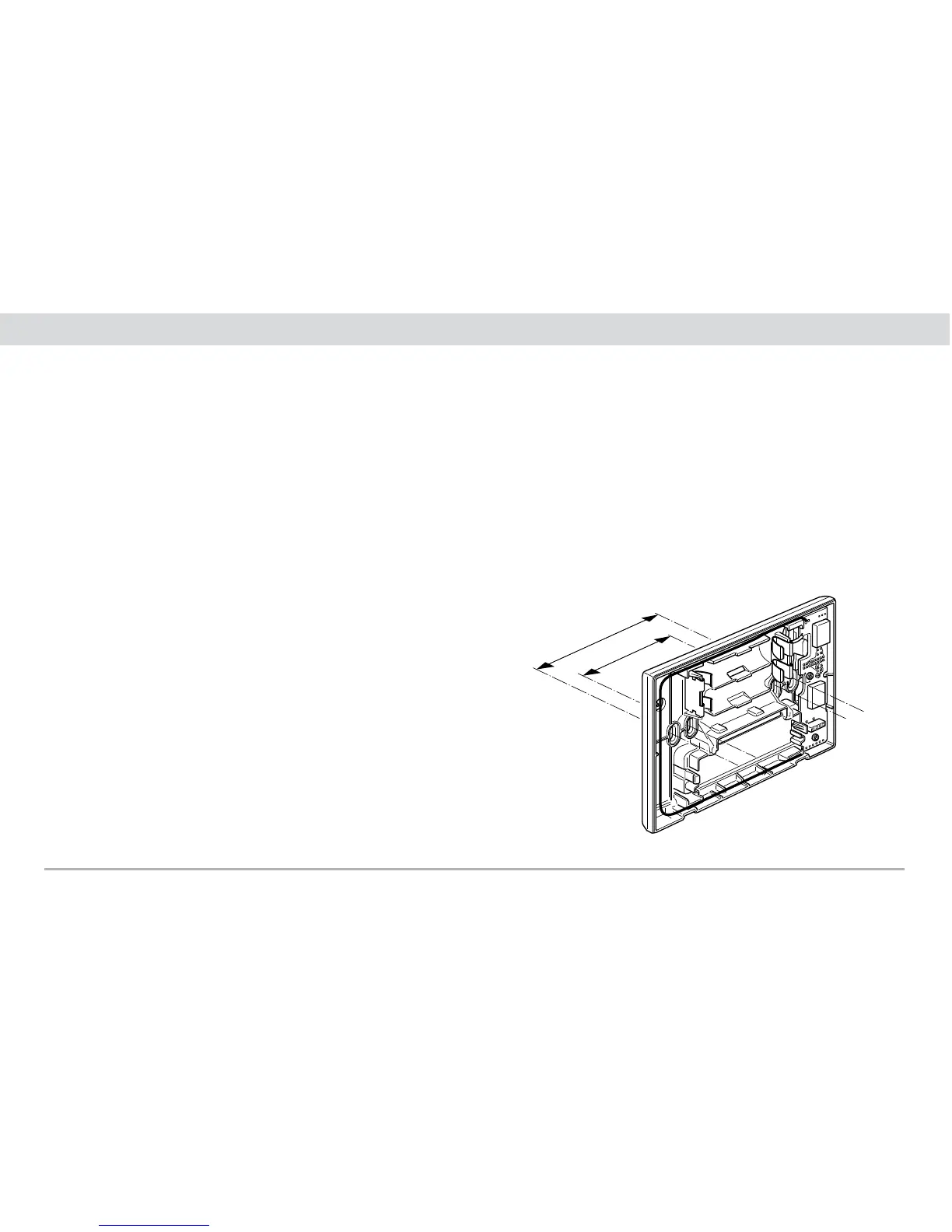
83,5 mm
60 mm
Fig. 3.1.1
2. CAMPO DI APPLICAZIONE
La base radio bidirezionale è adatta in implementazione di impianto
in cui non è possibile il collegamento filare e/o in caso di controllo
da remoto del cronotermostato mediante l’uso del Comunicatore
Telefonico GSM.
La Base Radio Bidirezionale è predisposta con 4 asole per il fissag-
gio diretto alla parete con tasselli ø 6 mm (non forniti), oppure per
installazione su scatole da incasso con fissaggio a viti con interasse
di 60 mm o di 83,5 mm (scatole rettangolari unificate 3 moduli)
(fig. 3.1.1). Deve essere utilizzata in luoghi asciutti non polverosi a
temperatura compresa tra 0 °C e +40 °C.

Table of Contents

Question and Answer IconNeed help?

Do you have a question about the Vimar radioclima and is the answer not in the manual?

Vimar radioclima Specifications

General IconGeneral
BrandVimar
Modelradioclima
CategoryThermostat
LanguageEnglish

Summary

3. INSTALLATION

3.1 Radio Transceiver Base Station

Details on wall-mounting the Radio Transceiver Base Station at a suitable height and distance from other components.

3.2 Radio relay actuator

Information on installing the radio relay actuator for EN 50022 rail mount, occupying six modules.

4. ADDITIONAL THERMOSTAT FUNCTIONS

4.1 Reset radio transceiver base station Menu

Procedure to restore the Radio Base Station to its original default configuration using the reset menu.

4.2 Installation Menu

Function for associating or excluding radio devices from the system using the installation menu.

4.3 Thermostat Manager Menu

Menu for programming or excluding secondary thermostats, managing their configuration.

5. SYSTEM CHARACTERISTICS

5.1 Low battery warning.

Signals for low battery status on the radio base station, requiring prompt replacement.

6. DEVICE CONFIGURATION

6.1 Autolearn of devices on primary thermostat (step 1)

Sets up communication between primary thermostat and radio relay actuator or Internal Communication Interface.

6.2 Duplication of primary thermostat to secondary ones (step 2)

Copies radio system configuration data from a primary thermostat to secondary thermostats (up to 7).

6.3 Associating a secondary thermostat with a relay radio actuator (step 3)

Assigns a relay actuator channel to a thermostat previously autolearned by the system.

7. ELIMINATION OF DEVICES

8. DEVICE RESET

10. EXAMPLES OF TYPES OF INSTALLATION

11. PRINCIPAL CHARACTERISTICS

12. INSTALLATION REQUIREMENTS FOR RADIO RELAY ACTUATOR

13. CONFORMITY TO REGULATIONS

Related product manuals