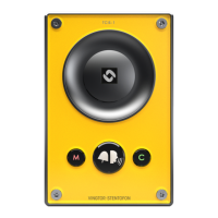
2 Station Connections
2.1 External Connectors on IP Station
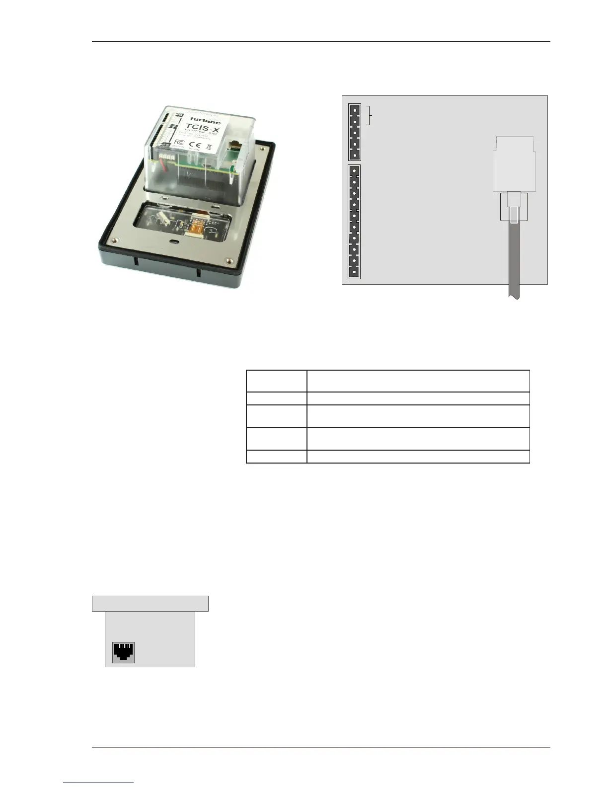
Figure 3 External Connectors on IP Station
The following table is an overview of the main connectors involved when
installing the Turbine IP Stations.
Ethernet / Power 10/100 Mbps Ethernet RJ-45 port for LAN (uplink) connection. Supports PoE
(802.3af). Draws power from either spare line or signal line.
Secondary Power 24 VDC (16 – 48 V) secondary power is provided from an external adapter.
Relays There is one Double Throw relay contact with 60W switching power. COM, NO,
NC contacts are provided. Max: 250VAC/220VDC, 2A, 60W.
Input/Output 6 general purpose I/Os are available. Each I/O can be congured as either
button input or LED driver.
Audio Line Out A balanced 600 ohm audio line out with induction loop signal
2.2 Power Supply
The Turbine Station supports Power over Ethernet (PoE, IEEE 802.3 a-f)
where power can be drawn from either the spare line or signal line.
If PoE is not available, the Turbine Station can be connected to a 24 VDC
local power supply.
2.3 Network Connection
There is one RJ-45 port located on the Turbine station that is used as the
PoE/LAN port.
PoE port
2.4 Input/Output Connections
There are 6 I/O connection options for the Turbine Station.
These connections are used as relay contacts for door lock control and
external I/O devices.
1
5
4
3
2
1
6
10
5
4
3
2
9
8
7
RJ-45
PoE
port
24 VDC for external secondary power
if PoE is not used. Pin 1 is positive.
- 5.3V (LED driver)
- GND
- Input/Output 5
- COM relay
- NC relay
- NO relay
- Input/Output 1
- Input/Output 2
- Input/Output 3
- Input/Output 6
- 600 ohm balanced line out +
- 600 ohm balanced line out -
- Input/Output 4
Ethernet Connection
 Loading...