32
Contents
Previous
Page
First
Page
Next
Page
Previous
View
General
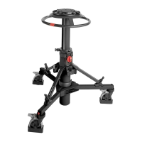
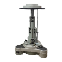
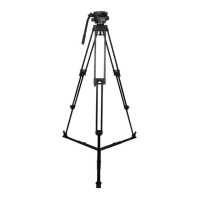
1 This section details procedures for disassembly and assembly of the Pro-6
HDV
pan and tilt head, Pozi-
Loc tripod and Pro-6
HDV
mid-level spreader. Reference is made in the procedures to figures in Section 6 -
Illustrated Parts List. Maintenance must be performed only by competent personnel in accordance with the
procedures laid down in this Maintenance Manual.
2 The head and tripod are constructed from precision components, many of which are of aluminium alloy.
Several of the assembly procedures require the use of specific sealants, adhesives or lubricants. It is advised
that only experienced and properly equipped personnel with access to all necessary materials and tools
should attempt to overhaul, repair or replace components on these heads and tripods. The consumable
materials required for work on heads and tripods are listed in Section 3 - Tools and Materials.
Pro-6
HDV
pan and tilt head
Disassembly
Platform
3 Remove the platform as follows (Fig 6.2):
3.1 If fitted, remove the camera mounting screws (1.1) and (1.2) from their stowage in the platform
(2.3).
3.2 Remove four screws (2.1), (2.2) securing platform (2.3) to left-hand and right-hand side covers.
Remove platform (2.3) from head.
4 To dismantle the platform (Fig 6.2):
4.1 Unscrew and remove the slide plate clamp knob (3.1) and push in the release button (3.6). Lift
the slide plate assembly (1) clear of the platform (2.3).
4.2 Remove the three screws (3.8) and remove the cover plate (3.7), side lock spring (3.4), clamp
spring (3.3), side load clamp (3.2), slide lock (3.5) and slide release button (3.6) from the underside of
the platform (2.3).
Right-hand side plate and balance mechanism
5 Remove the right-hand side plate and balance mechanism as follows (Fig 6.3):
5.1 Remove the right-hand side plate (1.9) from the head.
5.2 Slide the balance mechanism assembly (2) components—spring separator washers (2.1),
balance springs (2.2), spring cup washers (2.4), spring cups (2.3), (2.5) and sleeve strip (2.6)—off of
the spigot in the centre housing (3.3).
6 To dismantle the balance selector assembly (Fig 6.3):
6.1 Carefully prise out the balance knob bung (1.2), and remove the screw (1.3) and balance knob
(1.4).
6.2 Remove the two dowel pins (1.5) captivating the two balance selector pins (1.12).
6.3 Remove the balance selector cam (1.6) and retain the detent spring (1.8) and steel ball (1.7).