39
Contents
Previous
Page
First
Page
Next
Page
Previous
View
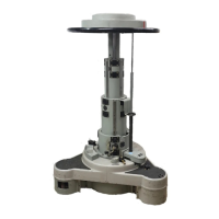
20.6 Install the balance knob (1.4), secure with screw (1.3) and fit balance knob bung (1.2).
20.7 If necessary lubricate the tilt bearing sleeve (1.11) with AGIP PV grease and install into the right-
hand side plate (1.9).
20.8 Install the right-hand side plate (1.9) over the balance mechanism, aligning the tilt bearing sleeve
(1.11) to the spigot on the centre housing (3.3).
Platform
21 To assemble the platform (Fig 6.2):
21.1 If required, use Kluberlub BE41-501 grease to lubricate the pivot lugs on the side load clamp
(3.2), slide lock (3.5) and side lock spring (3.4).
21.2 Install the side load clamp (3.2), slide lock (3.5), side lock spring (3.4) and release button (3.6)
into the underside of the platform (2.3).
21.3 If required, lubricate the clamp spring (3.3) with Kluberlub BE41-501 grease and carefully
position in the underside of the side load clamp (3.2).
21.4 Carefully align the recess in the underside of the cover plate (3.7) with the clamp return spring
(3.3) and secure the cover plate (3.7) in place using three screws (3.8).
21.5 If required, lubricate the clamp knob (3.1) with Kluberlub BE41-501 grease and install into the
platform (2.3).
22 To install the platform (Fig 6.2):
22.1 Position the assembled platform on the left-hand and right-hand side covers and secure with four
screws (2.1) (2.2).
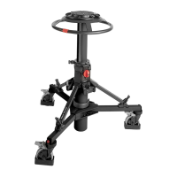
Pozi-loc tripod
General
23 The tripod legs are constructed using adhesive processes. The following procedures are the limit of
component replacement.
Replacing tripod legs
24 The legs are secured in the bowl assembly by pivot clamps. Each clamp is secured by a single screw.
Removal
25 Remove the tripod leg as follows (Fig 6.7):
25.1 If necessary, remove the hook (6), which passes through one of the leg pivot clamps (2) and
screws into the bowl assembly (1).
25.2 Remove the screws (4) and leg pivot washers (3) securing the leg pivot clamps (2) to the bowl
assembly (1).
25.3 Pull off the tripod leg. Note orientation and remove two leg pivot friction rings (7) and two leg pivot
washers (8).