12
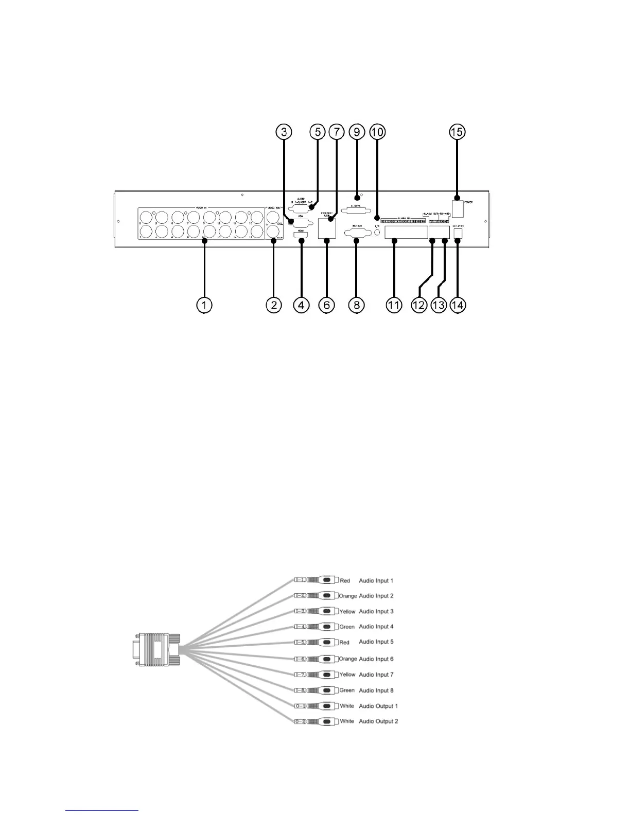
2.2 Back Panel
1. Video Input Connectors (1-16)
Connect system cameras to these BNC connectors. The internal 75Ω
termination is always ON.
2. Video Out (MAIN/CALL)
Connect TV monitor to the BNC connectors for main/call monitor display.
3. HDMI Connector
Connect HDMI monitor to the HDMI connector for main monitor display.
4. VGA Connector
Connect VGA monitor to the VGA connector for main monitor display.
5. Audio In/Out Connector (AUDIO IN 1-8, OUT 1-2)
Connect to Audio In 1-8/Out 1-2 Cable. The cable is as shown below.