13
6. USB Mouse Connector
Connect to USB 2.0 compatible mouse.
7. Ethernet Connector
Connect this unit to a 10/100Base-T Ethernet network through this port.
8. RS-232 Connector
Connect this connector to PTZ camera(s), GPS modem, or POS system.
9. eSATA Connector
Connect this port to external SATA storage device for HDD extension.
10. I/R Extension Connector (I/R, optional)
Optional I/R extension connector to receive signal from I/R remote
controller.
11. Alarm Input Connectors (ALARM IN 1-8)
Connect these connectors to external devices such as sensors or door
switches.
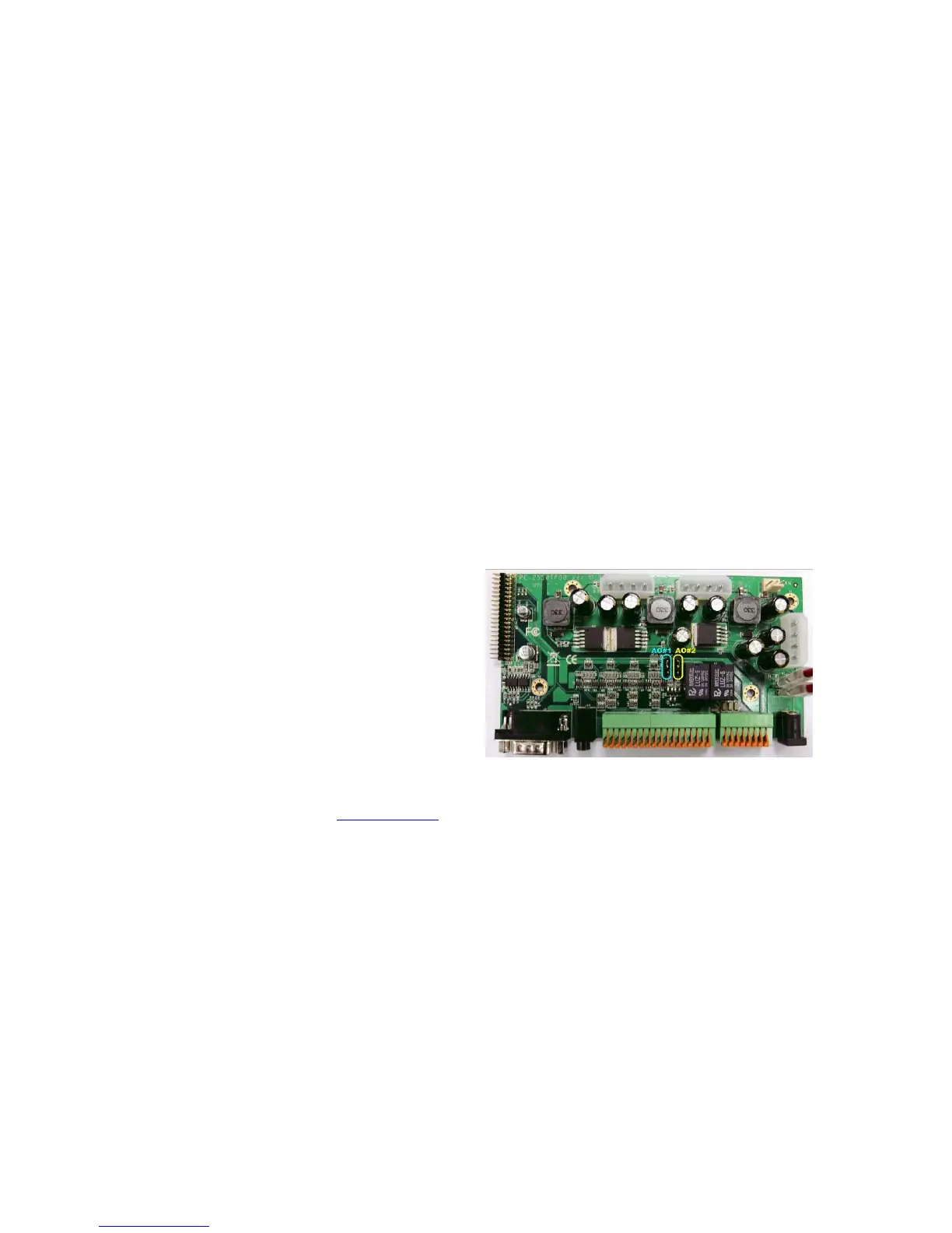
12. Alarm Output Connectors (ALARM OUT 1-2)
Connect these connectors to 2
Normally Closed(NC)/Open(NO)
alarm outputs. For NC or NO,
please set the jumper on the
internal I/O board. The default
setting is NO.
13. RS-485 Connector
Connect this connector to
RS-422/485 compatible PTZ camera(s) or keyboard. Please refer to the
manuals come with the RS-485 compatible devices for the correct settings.
Please refer to Appendix C for the Keyboard Control Protocol for the
digital video recorder.
14. Power Input (DC 12V)
Connect to DC 12V power source.
15. Power Switch (POWER)
Turn the power of this unit on/off.