7
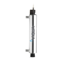
3.3 Controller Interface
The controller is equipped with the following features:
1. Audible alarm
2. Audible alarm mute
3. Replacement lamp counter reset
4. Lamp operation indicator
5. Controller operation indicator
6. Solenoid valve operation indicator
7. Fan operation indicator
8. Sensor reading indicator
9. Flow meter operation indicator
Firmware in the controllers monitors flow rate and sensor input for set point conditions.
Controllers will enter audible and visual alarm if the sensor input is too low given the
measured flow rate. Set points depend on the Adjustable Alarm Set Points (sec. 3.7.3).
0
50
100
150
200
250
300
350
0 5 10 15 20 25 30 35
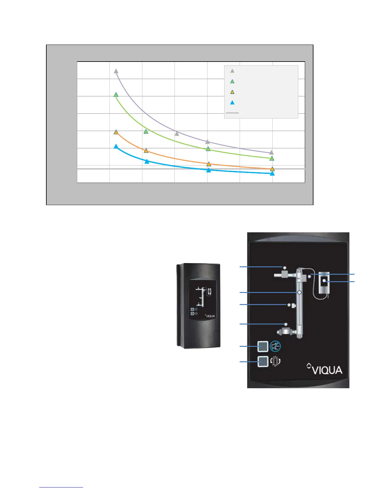
Dose (RED) (mJ/cm
2
)
Flow rate (gpm)
95% UVT
85% UVT
65% UVT
55% UVT
NSF Alarm Set Point