15
• Lamp Fault
• Ballast (Controller) Fault
• UV Sensor Fault
• Low UV Fault
Connection Logic Chart
Wire Output Terminal
UV System in
Normal Operation
UV System in Major
alarm/not powered on
RED
N.O. (Normally Open
Contact)
The Electrical path
between these
contacts are closed
The Electrical path
between these contacts
are open
BLACK
COM. (Common)
COM. (Common)
The Electrical path
between these
contacts are open
The Electrical path
between these contacts
are closed
GREEN
N.C. (Normally Closed
Contact)
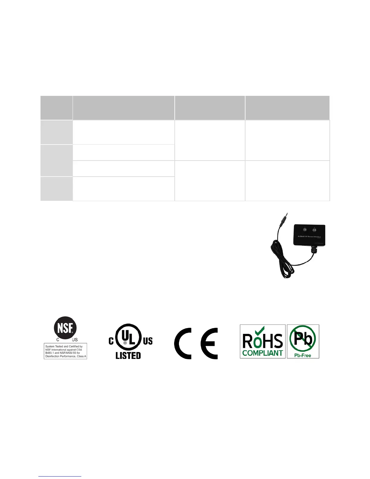
3.8.3 4-20 mA Interface
An optional 4-20 mA interface allows the user to read the current
output by the UV sensor or the flow meter. The interface can be
used to send information to other monitoring systems.
4.0 C
ERTIFICATIONS
All PRO systems are tested and certified to NSF Standard 55 Class A, UL, CE, RoHS,
and Low Lead standards.
5.0 WARRANTY
VIQUA warrants the system components to be free from defects in material and
workmanship for the time specified in the table below. During this time, VIQUA will
repair or replace, at its option, any defective parts covered by the warranty.