VIVOTEK
User's Manual - 7
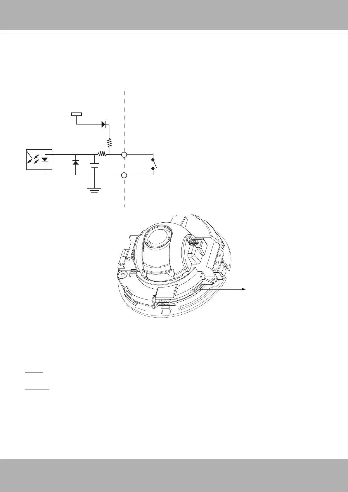
Digital Input Diagram
Please refer to the following illustration for the connection method�
3.3V
Digital input
DI+
DI-: Ground
DI-
Max. voltage: 40V
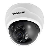
Hardware Reset
The reset button is used to reset the system or restore the factory default settings� Sometimes
resetting the system can return the camera to normal operation� If the system problems remain
after reset, restore the factory settings and install again�
Reset: Press and release the reset button. Wait for the Network Camera to reboot.
Restore: Press and hold the recessed reset button until the status LED rapidly blinks. Note that
all settings will be restored to factory default� Upon successful restore, the status LED will blink
green and red during normal operation�
Micro SD/SDHC Card Capacity
This network camera is compliant with Micro SD/SDHC 16GB / 8GB and other preceding
standard SD cards�
Reset Button