10TA Service Manual
10-5
OPTIONS AND ACCESSORIES
START/
HARVEST
F1
PLC I/O
STATUS
TUBE-ICE
--------------------------
F2
HISTORY
SETUP
MONITOR/
.
E
1012
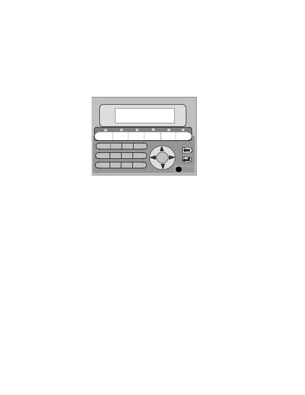
Fault History log (5 faults) will be created and can be viewed through the E150 Interface.
The PLC also logs (time and date) when a “power failure” occurs and when power is
returned.
Cycle History log (10 cycles) will also be created and viewed with the interface.
The PLC I/O Status screen can be used to view PLC Inputs and Outputs without opening
the control panel door. A Total cycle counter and hour meter can also be view with the.
.
Mitsubishi E1012 Operator Interface
FIGURE 10-2
Mitsubishi HMI
MITSUBISHI PLC
The Mitsubishi Programmable controller contains 14 inputs and 10 outputs on the base unit with
an additional 4 input and 4 outputs on an expansion module. The power supply for the unit can
be 100-240VAC, 50/60 Hz and is internally fused for 3A. The inputs are 24VDC internally fused
for 5-7mA and supplied by the PLC. All 24VDC control wiring is blue in color and is
distinguished from the red 240VAC or 120VAC control wiring. The outputs are externally fused
for 2A. Outputs 1 and 2 are dry contacts used for high side control interlock and conveyor
control. Outputs 0, 3-11 & 20-23 are relay type with 120V or 200/240 V connections.
The LED indicators on the right hand side of the Mitsubishi PLC indicate the power, run and
error status of the PLC. When power is on to the PLC and the run/stop switch is in the run
position the power and run indicators will be illuminated. A solid or flashing error light indicates
a processor or program error. The LED indicators on the upper right hand side of the PLC,
indicates the input status and LED indicators on the lower right hand side of the PLC indicate the
output status. If the input (X#) indicator is illuminated, then the PLC is receiving the input. If the
output (Y#) indicator is illuminated, then the PLC is sending the output. Use of these LED’s will
be helpful in troubleshooting the machine.