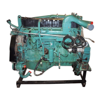
Group 25 Intake and Exhaust System Service Procedures
W2000732
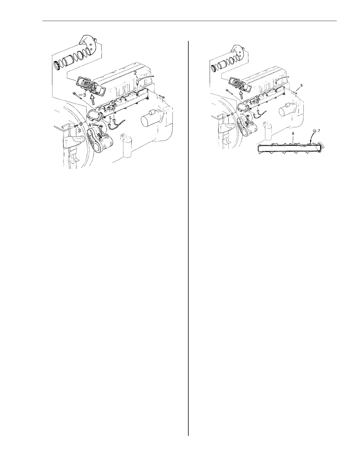
Fig. 35: Replacing intake manifold gasket
Removal
1
Remove the plastic ties from the elec-
tric cables under the intake manifold.
Disconnect the terminals from the sen-
sors for the charge air pressure and
the charge air temperature on the in-
take manifold.
2
Remove the boost pressure gauge
connection from the intake manifold.
3
Remove the bolt for the pre-heater, or
the spacer, from the fan shroud
bracket.
Remove the pre-heater, or the spacer,
from the intake manifold and set aside.
4
Loosen the alternator drive belt and re-
move the nut for the gear lever bracket.
Remove the alternator.
5
W2000733
Fig. 36: Replacing intake manifold gasket
Remove the intake manifold bolts and
carefully tap the manifold loose, using
a plastic-headed mallet.
6
Clean the sealing surfaces of the in-
take manifold and the cylinder head.
Install a new gasket.
Installation
1
Install a new seal on the compression
brake oil duct.
2
Apply a 2 mm (1/16 in.) bead of
sealant to the intake manifold. The
manifold must be installed and tight-
ened within 20 minutes after applying
sealant.
Note: Do not allow the sealant to enter
the oil duct of the compression brake.
2mm
(1/16 in.)
31