Group 25 Intake and Exhaust System Service Procedures
8
Reconnect the air cleaner hose to the
turbocharger.
9
Attach the turbocharger oil return pipe,
using new seals.
10
Apply parking brake and place shift
lever in neutral. Start the engine and
check for proper operation and leaks.
2516-03-04-01
Exhaust Manifold Gasket(s),
Replacement
(Turbocharger Removed)
Before working on a vehicle, set the parking brakes,
place the transmission in neutral, and block the
wheels. Failure to do so can result in unexpected
vehicle movement and can cause serious personal in-
jury or death.
WARNING
HOT ENGINE! Keep yourself and your test equipment
clear of all moving parts or hot engine parts and/or
fluids. A hot engine and/or fluids can cause burns or
can permanently damage test equipment.
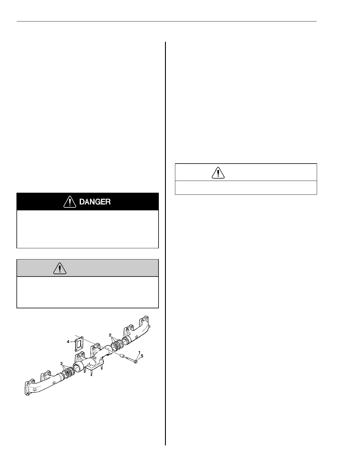
T2006979
Fig. 40: Exhaust manifold
Note: It is easy to get the wrong impression from ex-
haust manifold leakage (mixture of moisture and soot).
This mixture may drip down on the turbo and could eas-
ily be mistaken for an oil leak from the turbo.
Removal
1
Remove the bolts holding the exhaust
manifold and lift off the manifold.
2
Disassemble the exhaust manifold and
remove all sealing rings. Clean the ex-
haust manifold and the cylinder head.
Installation
3
Use compressed air to blow any
carbon out of the manifold. Then as-
semble the manifolds.
CAUTION
Wear appropriate eye protection.
Note: Three sealing rings must be in-
stalled at each side. Install the sealing
ring with the smallest diameter in the
middle.
4
Install the exhaust manifold using new
gaskets. Begin by lining up all three
manifold sections onto the cylinder
head, starting with section A.
Note: Make sure that the sleeves fit
correctly into the milling of the exhaust
manifold and install the gaskets with
the graphite surface facing the cylinder
head.
5
After applying anti-sieze to the mani-
fold bolts and turbo studs, screw the
bolts in by hand, starting with section
A and then sections B and C.
6
Tighten the bolts cross-wise starting
with section A, and then sections B
and C. Torque to 25 Nm (18 ft-lb). See
illustration, page 26
25 Nm
(18 ft-lb)
7
Begin the tightening sequence again;
however, raise the torque to 48 ± 8 Nm
(35 ± 6 ft-lb).
48 ± 8 Nm
(35 ± 6 ft-lb)
34