Group 25 Intake and Exhaust System Design and Function
D12C
The VEB solenoid has been moved to the center of the
rocker shaft. The oil supply is internal, rather than having
the external piping visible.
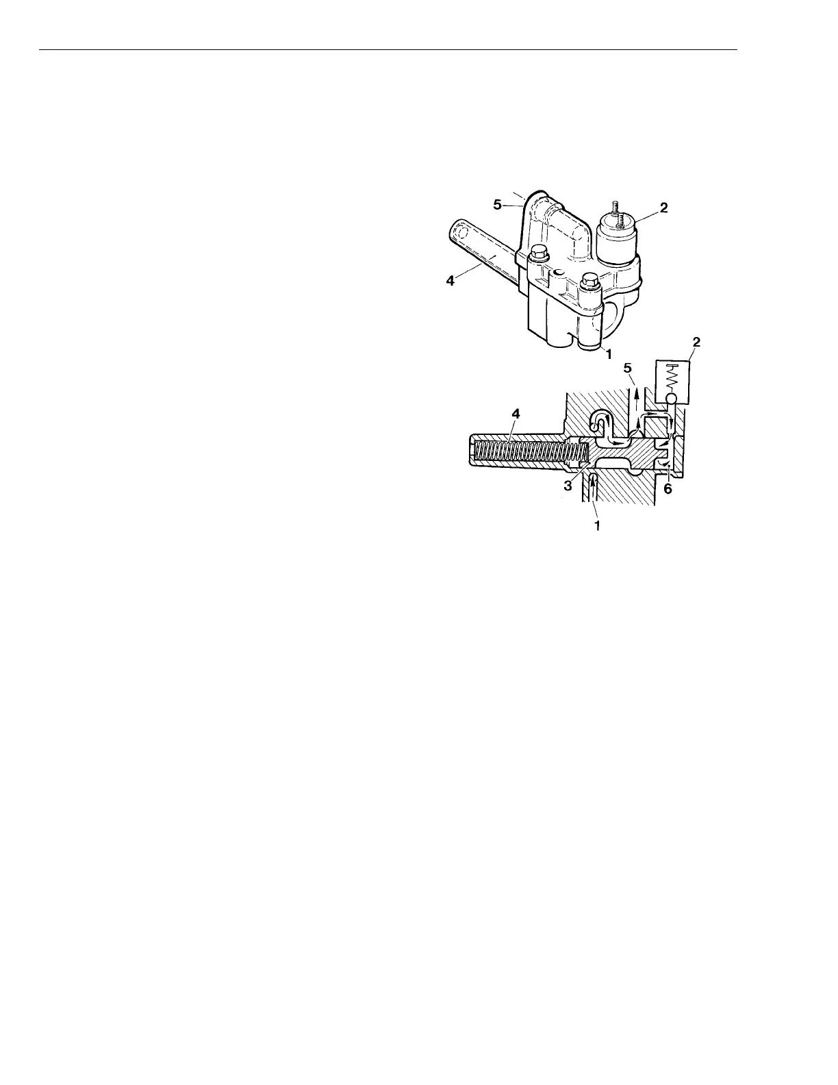
Control Valve
The control valve is mounted on the cylinder head under
the valve cover, and is connected to the oil system
ahead of the rocker arm shaft. Its purpose is to reduce
the oil pressure to the rocker arms while the engine is
operating (compression brake not activated).
There is always full system oil pressure to the control
valve intake (1) because the intake is connected via a
pipe to the lube oil gallery in the cylinder block. The oil
pressure to the rocker arm shaft can be increased via a
solenoid valve (2) mounted on the control valve, from ap-
proximately 100 kPa (14.5 psi) while the engine is
operating, to more than 200 kPa (29 psi) during com-
pression braking.
While the engine is operating, the oil pressure is reduced
after the control valve by the plunger (3) being held in
balance by the force of a spring (4) and the oil pressure
in the oil chamber (6) on the opposite side of the plunger.
When the solenoid valve is activated, the oil chamber (6)
is drained and the spring (4) presses the plunger (3) to
its end position. The plunger completely opens the oil
outlet (5) to increase oil pressure to the rocker arm shaft.
T2006835
Fig. 4: Control Valve
1 Oil inlet
2 Solenoid valve
3 Plunger
4 Spring
5 Oil outlet
6 Oil chamber
12