Group 25 Intake and Exhaust System Design and Function
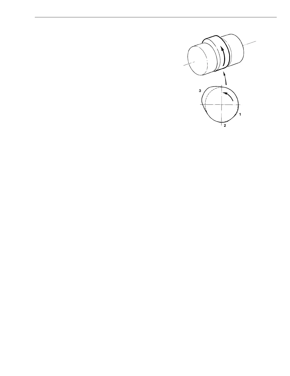
Camshaft on Engine with Compression Brake
The camshaft on an engine with a compression brake
has an induction lobe (1) and a decompression lobe (2)
— in addition to the normal exhaust lobe (3) — on each
cam profile for the exhaust valves.
The induction and decompression lobe lifting height is
0.8 mm (0.032 in.) above the basic circle, which is equiv-
alent to approximately 1.1 mm (0.043 in.) at the valve
bridge.
The induction lobe is positioned so that it opens the ex-
haust valves at the end of the intake stroke and holds
them open until the beginning of the compression stroke.
The decompression lobe is positioned so that it opens
the exhaust valves at the end of the compression stroke.
In order for the induction and decompression lobes to
open the exhaust valves, the valve clearance must be re-
duced to zero by the activation of the non-return valve
and plunger located in the rocker arm for the exhaust
valves.
T2006826
Fig. 5: Cam Shaft Profile
1 Induction lobe
2 Decompression lobe
3 Exhaust lobe
13