Group 25 Intake and Exhaust System Design and Function
Exhaust Rocker Arms
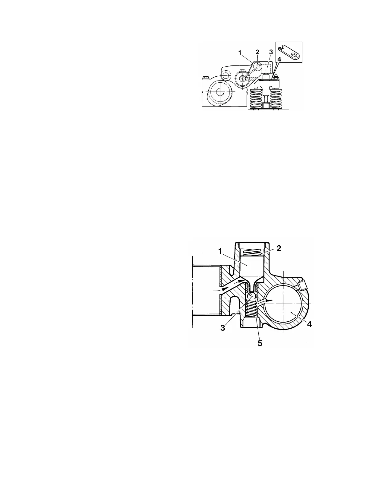
The exhaust rocker arms on an engine with a compres-
sion brake are larger than those on a conventional
engine.
The rocker arm includes a non-return valve (2) and a
plunger (3) with a pressure limiting valve, the purpose of
which is to regulate the oil flow during compression brak-
ing.
The rocker arm is held in its position against the valve
bridge with the help of a spring tab (1).
The valve clearance is greater than that on an engine
without a compression brake, because the induction and
decompression lobes must not open the exhaust valves
while the engine is in normal operating mode (compres-
sion brake not activated).
Valve adjustment is carried out with shims which are
placed on the valve bridge.
Note: A maximum of two shims are allowed to obtain
proper valve clearance.
W2003502
Fig. 6: Rocker arm assembly, side view:
1 Spring tab
2 Non-return valve
3 Rocker arm plunger
4 Shims
Non-Return Valve
The engine brake has a non-return valve, consisting of a
plunger (1), spring (2) and a ball (3) in the rocker arm.
When oil from the rocker arm shaft enters the valve, the
movement of the plunger is determined by the spring
force and the oil pressure.
When the oil pressure is low — approximately 100 kPa
(14.5 psi); the control valve is in its normal engine oper-
ating position — the plunger (1) will not move out of its
rest position because the oil pressure is not sufficient to
overcome the spring force. The plunger pin prevents the
ball (3) from entering the seating area, and the oil can
then flow freely through the valve in both directions.
When the control valve takes up the position for com-
pression braking, the oil pressure increases to the
non-return valve. The spring force in the non-return valve
is such that when the oil pressure exceeds approxi-
mately 200 kPa (29 psi), the spring force is overcome
and the plunger (1) moves so that it no longer influences
the ball (3). The spring (5) presses the ball (3) against
the seat and prevents the oil contained above the
plunger (4) from flowing past the ball (3). This forms high
oil pressure above the plunger (4).
T2006834
Fig. 7: Rocker arm assembly, top view:
1 Plunger
2 Spring
3 Ball
4 Rocker arm plunger
5 Spring
14