Group 25 Intake and Exhaust System Service Procedures
7
Remove the bolts holding the cover,
the heat shield and the securing
flange.
8
T2006744
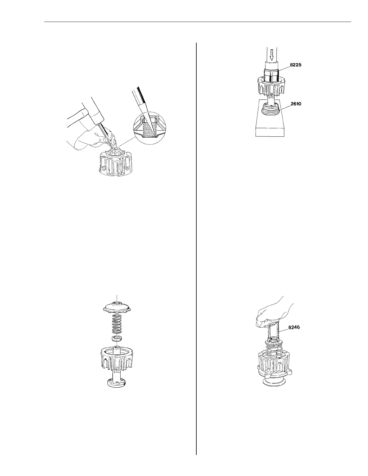
Fig. 46: Removing spring holder
Carefully tap out the spring holder that
secures the spring and the seal (9,
Fig. 44: Exhaust pressure governor,
page 36).
9
Clean all parts and replace any that
are damaged or worn.
Assembly
1
T2006745
Fig. 47: Assembly
Install the plunger rod into the housing
from behind so as to center the spring
holder. Install a new seal with the
beveled edge facing inside the hous-
ing. Install the spring and a new spring
holder.
2
T2006746
Fig. 48: Plunger rod installation
Put the plunger rod onto drift 9992610
in a press. Using drift 9998225, press
on the spring holder until it bottoms in
the housing. Remove the plunger rod.
Check to make sure that the spring
holder is correctly centered.
9992610
9998225
3
Install the securing flange, the heat
shield and the cover. Tighten the bolts
to 13 ± 2 Nm (10 ± 2 ft-lb).
13 ± 2 Nm
(10 ± 2 ft-lb)
4
Install the shutter, spring and plunger
rod into the housing.
5
T2006748
Fig. 49: Depressing spring
Compress the spring by hand, making
sure that the shutter shaft and plunger
rod fit together and that the plunger
rod fits correctly into the seal. Stop ap-
plying pressure if undue resistance is
felt. Install the valve collets.
37