Electronic control system, description
Regarding: L60F, L70F, L90F
Vehicle electronics, general
52, 3 4
1
V1048627
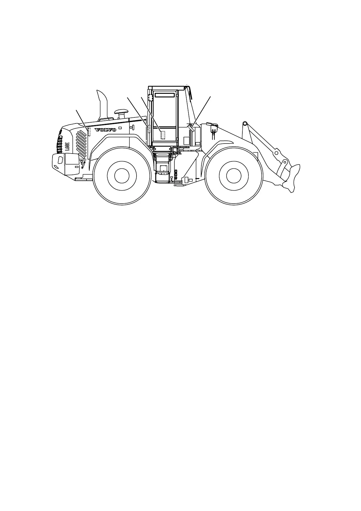
Fig.2 Position of control units
1 Engine control unit E-ECU (MID128)
2 Vehicle control unit V-ECU (MID187)
3 Vehicle control unit V2-ECU (MID249)
4 Climate control unit ECC (MID146)
5 Instrument control unit I-ECU (MID140)
The machine electronics contain five control units that communi‐
cate with each other via two data buses. Each control unit pro‐
cesses values from sensors and operating controls, and controls
components so that desired function is obtained.
Control units included in the system are the instrument control
unit I-ECU, vehicle control unit V-ECU, vehicle control unit V2-
ECU, engine control unit E-ECU, and climate control unit ECC.
Machine electronics facilitate troubleshooting with a well-
designed and expansive diagnostic system. In case of electrical
malfunctions/errors, the operator receives a message on the
information panel.
For service personnel, the service tool VCADS Pro can be
plugged into sockets located by the electrical distribution box
behind the operator's seat.
Instrument control unit I-ECU is located in the instrument panel
and contains software for presenting operator information on the
information panel, including warning and control lights. The con‐
trol unit receives information from the other control units via data
bus.
Engine control unit E-ECU is located on intermediate wall in the
engine compartment and contains software for controlling engine
functions. The control unit receives information from the engine's
own sensors as well as from a data bus. The control unit also
sends information to the other control units via data bus.
10