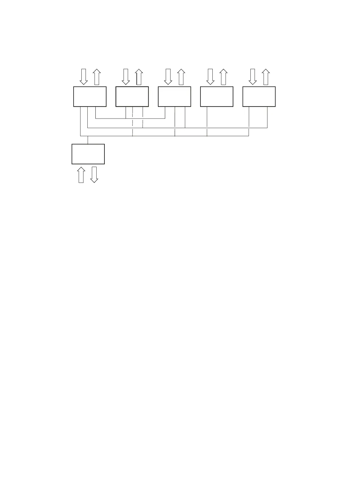
Communication with data buses
Regarding: L60F, L70F, L90F
VP
E-ECU
CAN1/J1939
J1587 708/1
V1047172
V-ECU
CAN2/J1939
I-ECU V2-ECU ECC
MID 187MID 140 MID 249 MID 128MID 146
Fig.3 Communication
ECC Electronic climate control unit
E-ECU Engine control unit
I-ECU Instrument control unit
V-ECU Vehicle control unit
V2-ECU Vehicle control unit
VP Service socket for VCADS Pro
General
In principle, the machine electronics are based on all communi‐
cation between control units in the system taking place via two
data buses. The machine's control units are connected to the
buses to enable communication with each other.
Communication between the different control units as well as
reporting from control units to service sockets takes place on data
buses CAN1/J1939 and J1587/1708.
The buses follow SAE standards and consist of two pair-twisted
cables. The purpose of the twisted cabling is to protect the bus
from electrical interference.
If an error or malfunction should occur in any system, a signal is
sent out on the information bus which makes it possible to read
off the information either in the information display or with VCADS
Pro. In VCADS Pro, MID-designations (Message Identification
Description) are used for the control units.
The figure above shows the principle for how the control units and
service sockets are connected to the buses.
12