Pressure test fan pump: Press SELECT and the figure changes
to the figure with rpm.
To return to previous figure, press ESC.
To perform pressure test, see
263, Pump 3 (P3) standby pres‐
sure, checking and adjusting (LS-line removed)
.
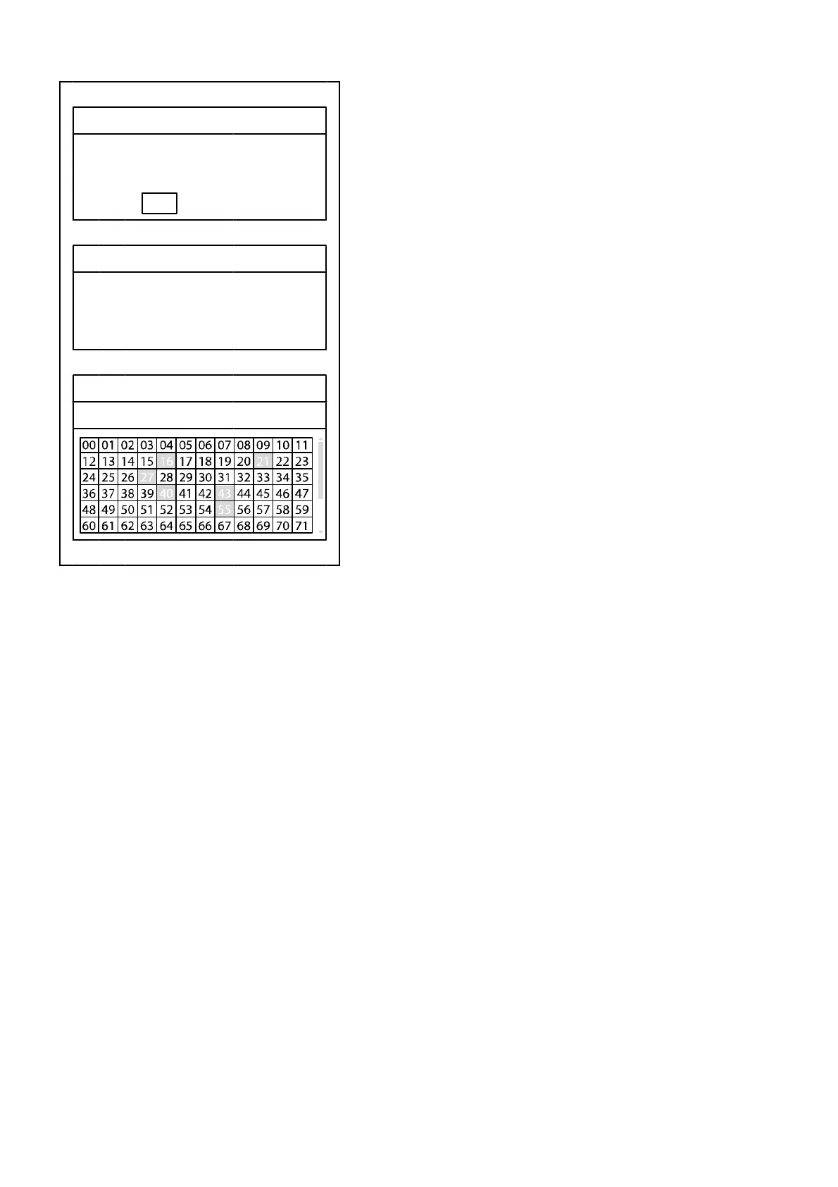
I/O-List
Select control unit and press SELECT.
- I-ECU: Instrument control unit
- V-ECU: Vehicle control unit
- V2-ECU: Vehicle control unit 2 (if the machine is equipped with
CDC).
Status for digital inputs and outputs on the ECUs is shown on the
information panel in the form of a matrix according to example for
V-ECU. The connector's pin number corresponds to the same
number in the figure, e.g., VA1 is shown in the figure as 01.
- High signal on digital input (DI) and digital output (DO) is shown
with yellow filled rectangle and pin number.
- Low signal on digital input (DI) and digital output (DO) is shown
only with pin number.
- Analogue, frequency, and PWM signals are not shown as high,
instead only with pin number.
- In case of electric problem, “o” is shown for open circuit and “s”
for short-circuiting.
- If input or output is not used, “–” is shown.
Pressure test fan pump
Engine rpm rpm
Fan rpm rpm
close:
ESC
I/O-List
I-ECU
V-ECU
V2-ECU
I/O-List
V-ECU (1/2)
54