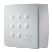
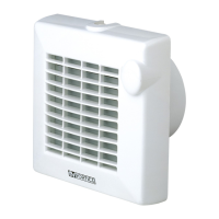
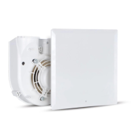
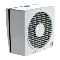
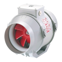
Typical applications
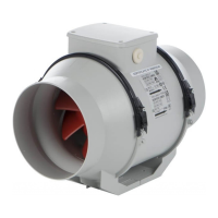
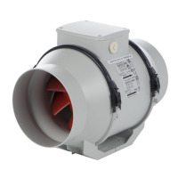
LINEO 250 ES / LINEO 315 ES: fig. 1-2
Installation
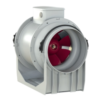
Fig. 3 ÷ 25.
Fig.3: B= Air flow direction data plate; C= Inlet; D= Outlet.
Wiring diagram
LINEO 250 ES: Fig. 16 ÷ 20 LINEO 315 ES: Fig. 21 ÷ 25.
Initial configuration
The installer must configure appliance operation by following the steps described later on.
Selecting the product model: see below. This step is carried out in the factory; the instructions provided in this
booklet may only be of use if it becomes necessary to reset the status following accidental tampering with the
dip-switch.
Selecting the operating mode: see below. There are two modes: with two speeds V1 and V2, which can be
selected via an external switch, or with speed that can be adjusted via an external potentiometer.
Setting the V1 and V2 values (for two-speed operating mode)
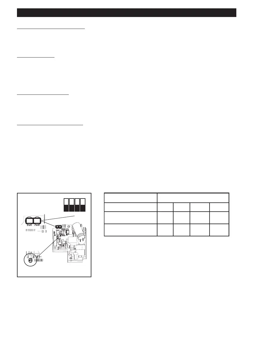
Selecting the product model
The model is selected by setting the dip-switch 1 indicated in the figure as described in the table below.
13
ENGLISH
Model SW1
Int. 1 Int. 2 Int. 3 Int. 4
LINEO 250 ES OFF ON ON OFF
LINEO 315 ES OFF ON ON ON
 Loading...