24
Installation Manual
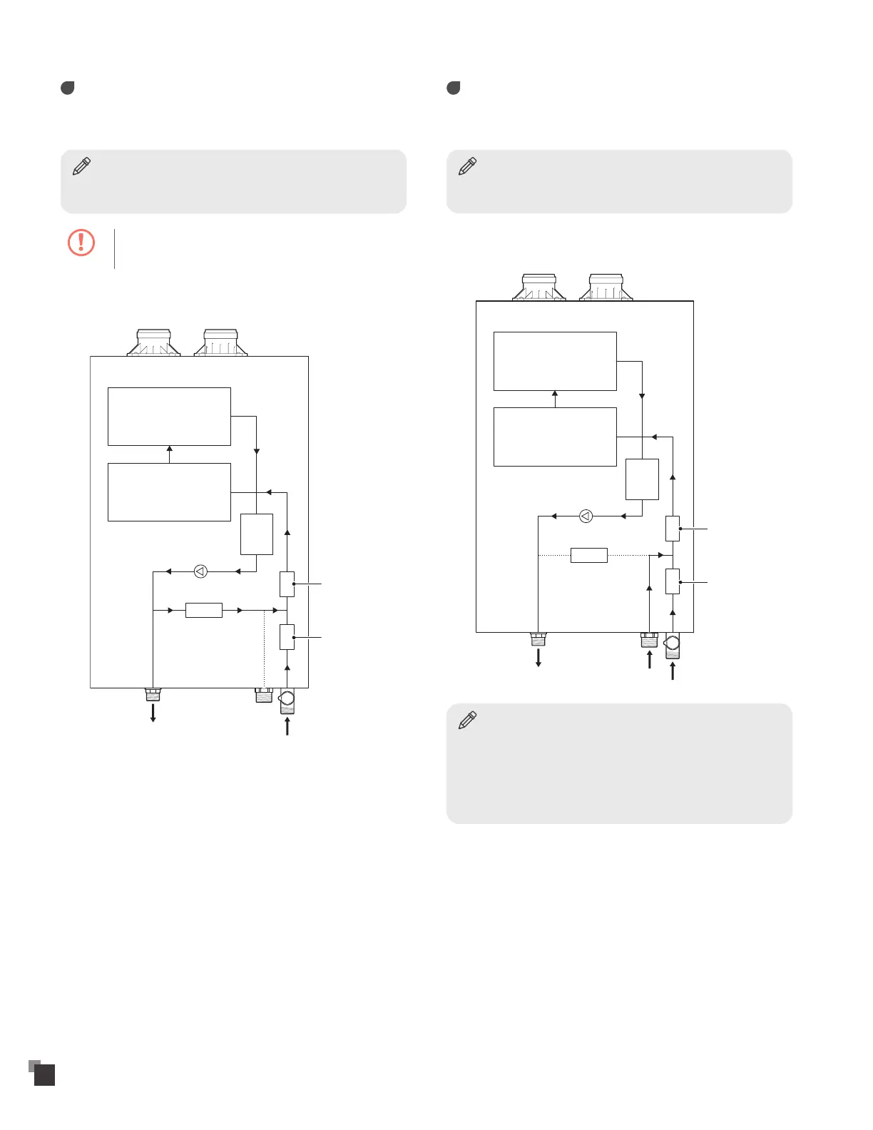
Internal recirculation mode ("VRP" model
only)
• Set the DIP switches to internal recirculation mode:
Notice
For more information about setting the DIP switches, refer to "Setting the
DIP Switches" on page 47.
Caution
Do not remove recirculation cap.
• The following diagram shows the internal recirculation flow:
Buffer
tank
Bypass
control valve
Open
Hot water
outlet
Recirculation
inlet
Cold water
inlet
Flow sensor
Flow control
valve
Primary heat
exchanger
Secondary heat
exchanger
External recirculation mode ("VRP" model
only)
• Set the DIP switches to external recirculation mode:
Notice
For more information about setting the DIP switches, refer to "Setting the
DIP Switches" on page 47.
• The following diagram shows the external recirculation flow:
Buffer
tank
Bypass
control valve
Close
Hot water
outlet
Recirculation
inlet
Cold water
inlet
Flow sensor
Flow control
valve
Primary heat
exchanger
Secondary heat
exchanger
Notice
When using a recirculation mode, by keeping the water in the hot water
supply pipe hot, you can get instant hot water when you turn the tap
on. On the other hand, there will be some minor efficiency loss, as a
result of the water heater maintaining a steady temperature within
the circulation loop, although in many cases, higher gas usage will be
compensated for by lower water usage.