47
Setting the DIP Switches
Setting the DIP Switches
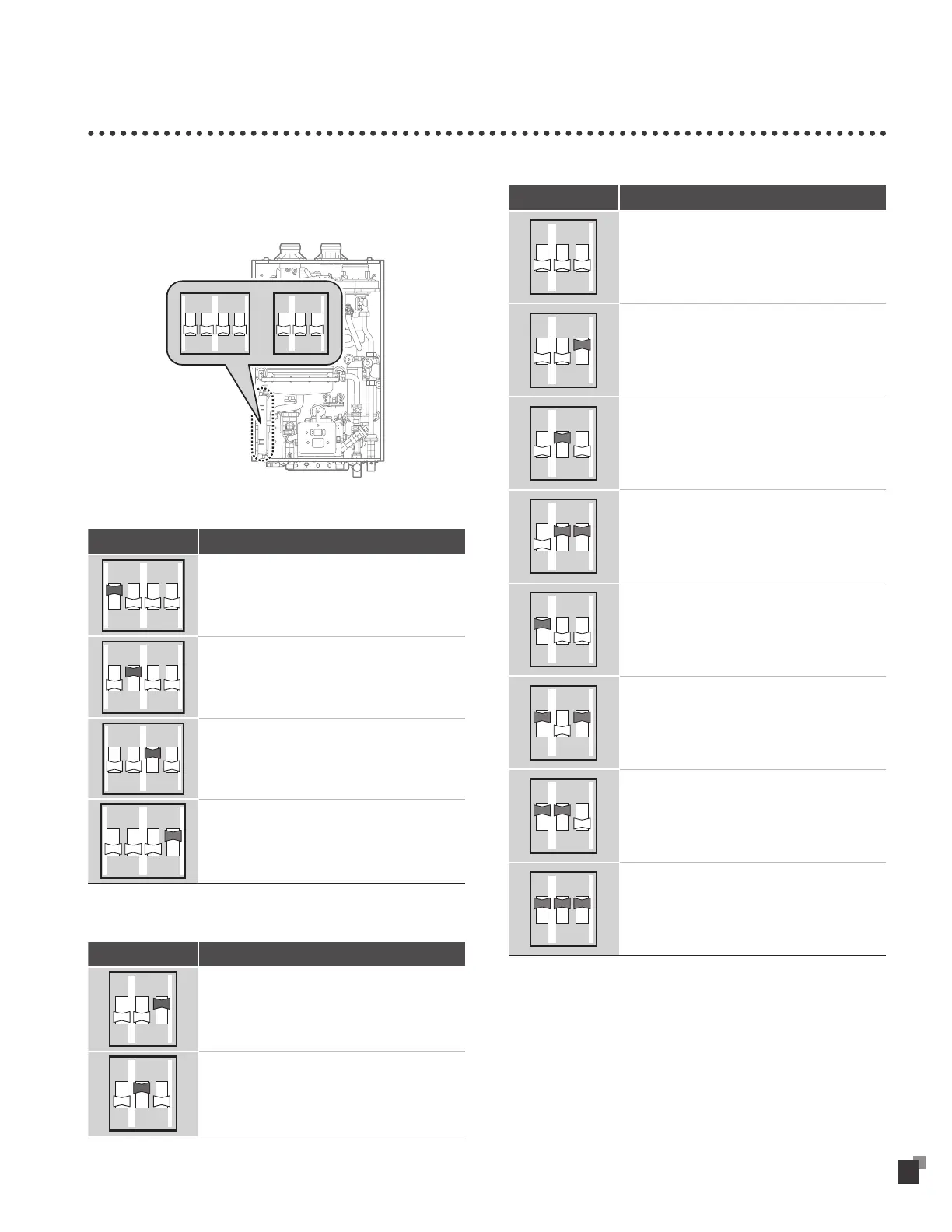
The water heater has a DIP switch on the main circuit board (PCB).
There are two sets of DIP switches that control the cascade system
of the water heater. Set the DIP switches appropriately, depending
on the installation environment.
1 2 34
ON
1 2 3
ON
4-switch panel (SW1)
Switch Function
1 2
ON
Recirculation mode for VD-100
1 2
ON
Internal recirculation mode ("VRP" model only)
1 2
ON
External recirculation mode ("VRP" model only)
1 2
ON
Cascade operation
3-switch panel (SW2): Cascade operation Off
Switch Function
1 2 3
ON
Minimum heat capacity operation.
1 2 3
ON
Maximum heat capacity operation
3-switch panel (SW2): Cascade operation On
Switch Function
1 2 3
ON
One water heater is in use for the cascade system
(only when cascade system is set in SW1).
1 2 3
ON
Two water heaters are in use for the cascade
system (only when cascade system is set in SW1).
1 2 3
ON
Three water heaters are in use for the cascade
system (only when cascade system is set in SW1).
1 2 3
ON
Four water heaters are in use for the cascade
system (only when cascade system is set in SW1).
1 2 3
ON
Five water heaters are in use for the cascade
system (only when cascade system is set in SW1).
1 2 3
ON
Six water heaters are in use for the cascade system
(only when cascade system is set in SW1).
1 2 3
ON
Seven water heaters are in use for the cascade
system (only when cascade system is set in SW1).
1 2 3
ON
Eight water heaters are in use for the cascade
system (only when cascade system is set in SW1).