30
Installation Manual
Non-direct
If, at any time, the installation location could experience negative
pressure, there is a possibility of back-drafting cold air through
the water heater’s heat exchanger. This situation could lead to the
freezing of the heat exchanger and malfunction of the water heater.
However, building codes in most jurisdictions disallow negative
pressures in residences. In a home with a well-balanced air supply,
the heat exchanger should not be in danger of freezing. Because
the cause of back-drafting is not considered a manufacturing
problem, any freezing damage which occurs from back-drafting
will not be covered by the VST warranty. If there is any question
about the possibility of back-drafting in the installation location,
use a direct venting system for the water heater. When installed in
a manufactured home (mobile home), all combustion air must be
supplied from the outdoors as described on page 27. When using
non-direct venting, maintain non-direct vent clearances shown on
page 29 as required by ANSI Z21.10.3 and the National Fuel Gas
Code, ANSI Z223.1/NFPA 54, and CAN/CSA B149.1 Natural Gas and
Propane Installation Code.
For other than a direct vent appliance, the appliance must be
located as close as practicable to a chimney or gas vent.
If the appliance is installed without air intake pipe, the category is
IV. "This water heater requires a special venting system. Refer to the
installation instructions for parts list and method of installation."
When installed in a manufactured home (mobile home), the screen
for openings specified shall be of metal with no less than ¼ in (6.4
mm) mesh.
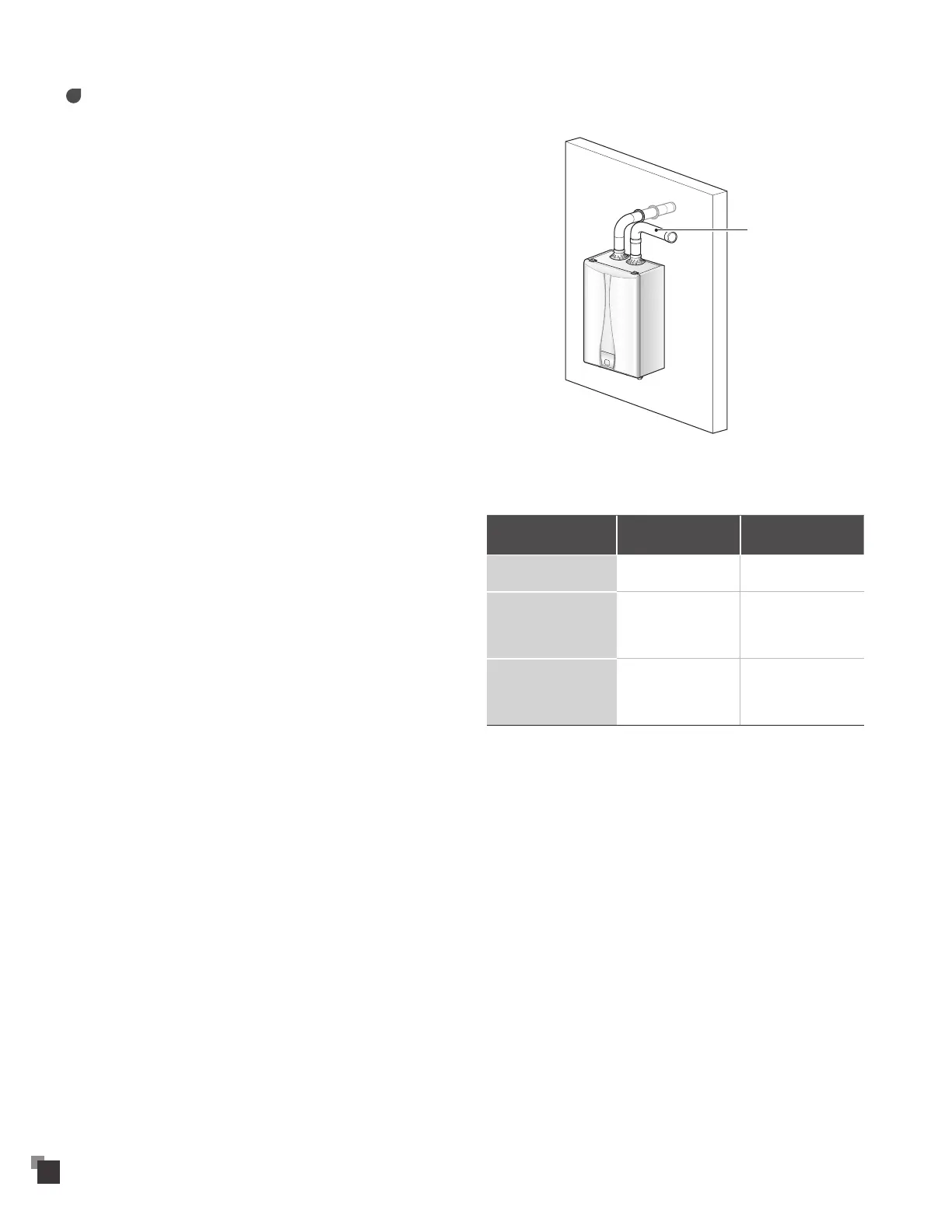
To use non-direct venting for the water heater:
• Insert the elbow into the intake air duct.
Intake pipe
• Provide two openings to allow for circulation of combustion air
as specified by ANSI Z223.1/NFPA 54 or CAN/CGA B-149.1:
VRP-150
VRS-150
VRP-199
VRS-199
Maximum Input
(BTU/H)
150,000 199,000
If outdoor make up air
is provided, a minimum
free area of 1 in
2
, per
4,000 BTU/H
40 in
2
10“(W) x 4” (H) or
7“ round
50 in
2
10“ (W) x 5” (H) or
8“ round
If indoor make up air is
provided, a minimum
free area of 1 in
2
per
1,000 BTU/H
150 in
2
12 1/4“ (W) x
12 1/4“ (H)
199 in
2
14 1/4“ (W) x
14 1/4“ (H)