37
Common Vent System Information (Optional)
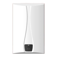
Clearances Between Multiple Units
• Ensure that the installed water heaters satisfy all installation
clearances provided in the manual. It is essential that there is
sufficient clearance space for the common vent system to work
properly.
• The water heater units can be mounted either IN-LINE or BACK
TO BACK.
VST Modular Configuration with Rack System
IN-line Setup Back to Back Setup
Clearances Chart for Common Vent
Application
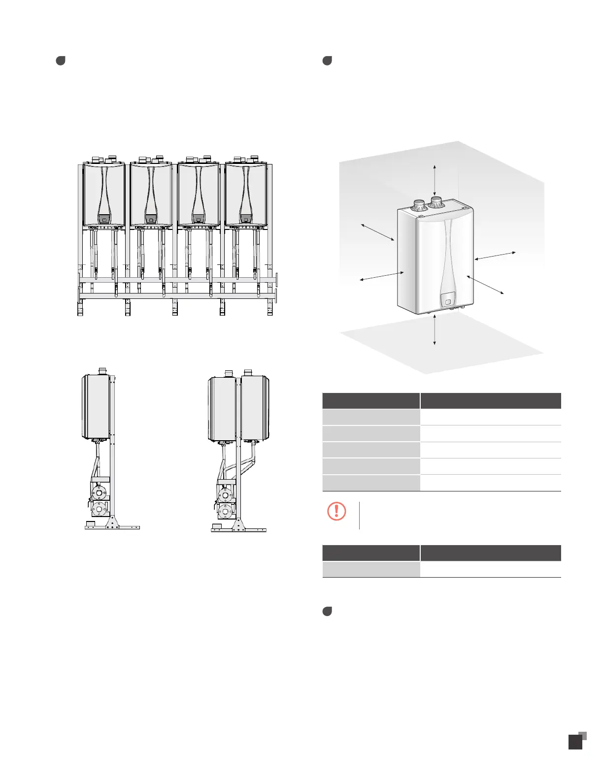
• The water heaters should be installed in an area that allows
for service and maintenance access to utility connections,
piping, filters, and traps. Ensure the following clearances are
maintained:
Top
Back
Front
Side
Side
Bottom
Clearance From Wall Mounting
Top 36 inches (914 mm) min.
Back 0.6 inches (15 mm) min.
Front 24 inches (609 mm) min.
Sides 3 inches (76 mm) min.
Bottom 12 inches (300 mm) min.
Caution
Do not install the water heaters on carpeting.
Local Recommended Vent Materials
Bottom 12 inches (300 mm) min.
Selecting Vent Pipe Materials
• Consult the following chart or the most recent edition of
ANSI Z223.1/NFPA 54, as well as all applicable local codes and
regulations when selecting vent pipe materials. This appliance
should be vented with materials approved for category IV gas
appliances.