60
Installation Manual
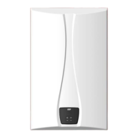
Piping sizes
When plumbing a cascade system, consider the following pipe
diameters and flow rates (note that flow rates above 6.6 ft/s may
cause pipe erosion). These specifications may vary depending on
installation conditions.
Qty
T=54ºF
Flow Rate
(GPM)
Water
Velocity (ft/s)
Pipe
Diameter (mm/in)
1 7.07 4.71 20A 3/4"
2 14.13 5.52 25A 1"
3 21.20 5.44 32A 1 1/4"
4 28.26 5.12 40A 1 1/2"
5 35.33 6.40 40A 1 1/2"
6 42.39 4.42 50A 2"
7 49.46 5.15 50A 2"
8 56.52 5.89 50A 2"
9 63.59 4.30 65A 2 1/2"
10 70.65 4.77 65A 2 1/2"
11 77.72 5.25 65A 2 1/2"
12 84.78 5.73 65A 2 1/2"
13 91.85 6.20 65A 2 1/2"
14 98.91 6.68 65A 2 1/2"
15 105.98 5.02 80A 3"
16 113.04 5.35 80A 3"
17 120.11 5.69 80A 3"
18 127.18 6.02 80A 3"
19 134.24 6.36 80A 3"
20 141.31 6.69 80A 3"
21 148.37 3.99 100A 4"
22 155.44 4.18 100A 4"
23 162.50 4.37 100A 4"
24 169.57 4.56 100A 4"
Notice
• The table above is based on model VRP-199.
• When installing more than twenty four water heaters for a cascade
system, please call 1-800-761-0053.
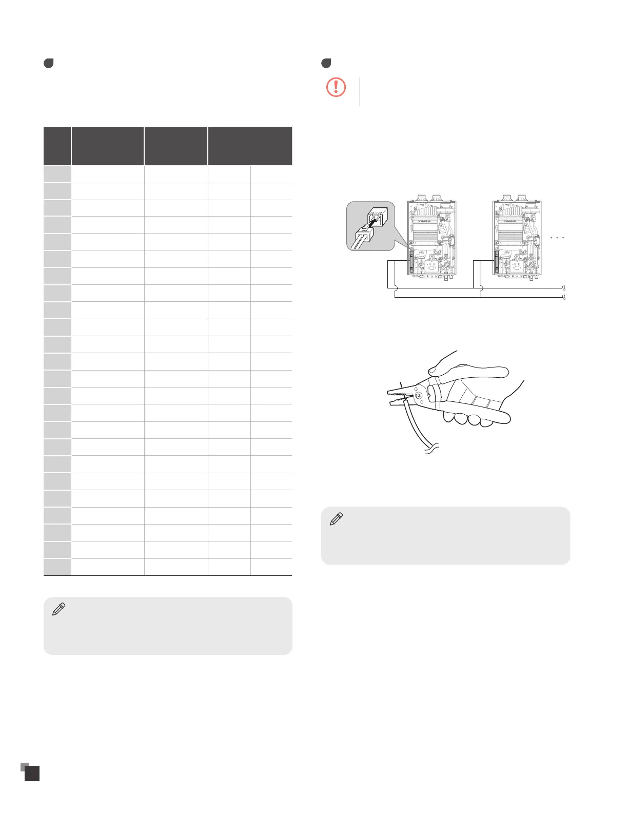
Communication cables
Caution
To avoid electric shock, turn off the water heater while
connecting the wires.
Up to 8 water heaters can be connected with cascade
communication cables.
To connect the cascade communication cables:
1
Connect the cascade communication cable connector to the
connector socket on the PCB assembly.
Red(+)
2
Remove the plastic insulation from opposite ends of the
cascade communication cable.
3
Connect the cascade communication cables by matching the
colors (red, green).
Notice
Set the DIP switches after connecting the cascade communication
cables. For more information about setting the DIP switches, refer to
"Setting the DIP Switches" on page 47.