7 Components and operator's controls
100_0202_cp_0011.fm 19
7 Components and operator's controls
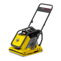
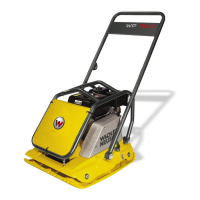
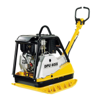
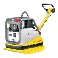
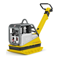
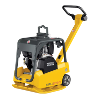
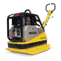
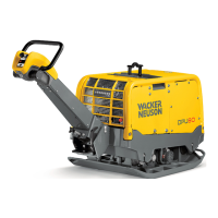
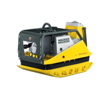
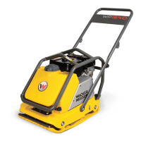
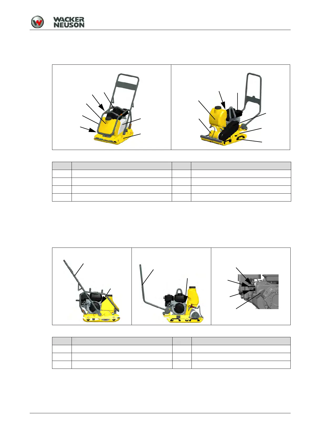
7.1 Components
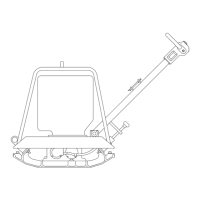
7.2 Operator's controls
Always keep the display and operator's controls on the machine clean, dry, and free of oil and grease.
Operator's controls, such as the ON/OFF switch, throttle control handles, etc. may not be locked,
manipulated or changed without permission.
WP VP
Item Designation Item Designation
1 Drive motor 5 Belt guard
2 Base plate 6 Water tank (optional)
3 Exciter 7 Handle (VP - position depends on versions)
4 Protective frame (WP) 8 Nameplate
WP VP WP/VP
Item Designation Item Designation
1 Control handle 4 Fuel cock
2 Throttle lever 5 Choke lever
3 Handle recoil starter 6 Engine switch