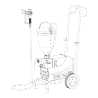
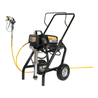
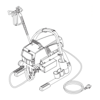
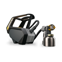
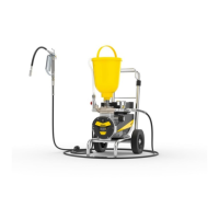
1 Spray gun
2 High-pressure hose
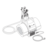
3 Outlet valve
4 Socket, max. load 1000 Watt
5 Inlet valve in coating material inlet
6 Connection for cleaning
with the spray gun
7 Suction pipe
8 Return pipe
9 Filter, size of mesh 1 mm
10 Dust protection cap
11 Oil measuring stick under
the oil screw plug
12 Relief valve
Symbols:
Spraying p
Circulation k
13 Control lamp shows that the unit
is ready for operation
14 ON/OFF switch
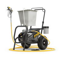
15 Pressure regulating valve
16 Manometer
17 Shaft locking device
18 Eyelet stop for the spray gun
19 Extractable shaft
20 Upper hopper, capacity 5 litres
21 Return pipe
(not positioned parts as in fig. 5)