Assembly Instructions
23
Carrier Frame
Tube Sockets
Deck Support Arms
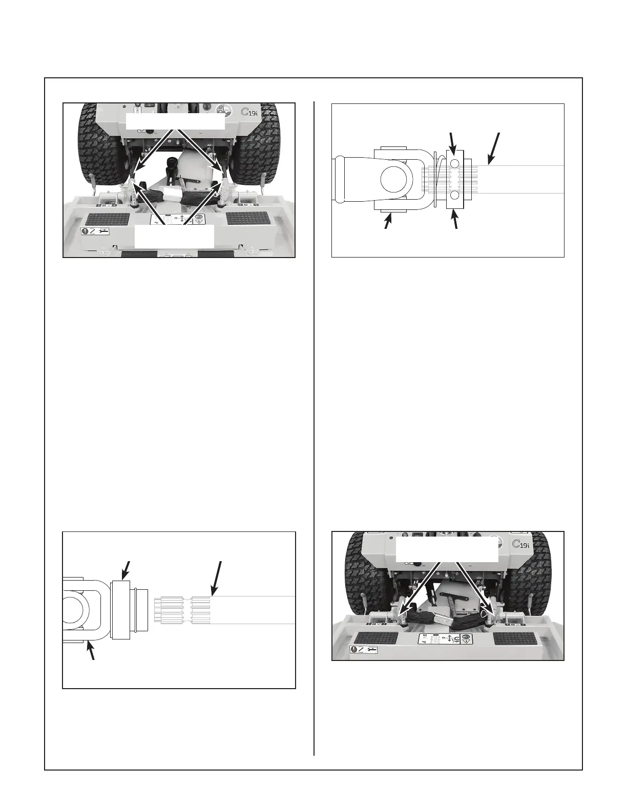
Mower Deck Installation
4. Engage the deck carrier frame tube sockets on
the tractor support arms. Refer to Mower Deck
Installation photo for socket location. Slide the
deck onto the support arms approximately 3 in.
(76 mm).
5. Reaching under the tractor, slide the PTO cou-
pler tube onto the tractor’s PTO drive shaft.
Make sure the ring has “snapped” securely on
the spline shaft.
IMPORTANT: To prevent damage to the mower,
make sure the PTO quick disconnect is securely
locked on the tractor, with the locking balls fully
seated in the groove and the ring in the locked
position (refer to the Quick Disconnect Ring
“Locked” Position illustration). After installa-
tion, pull on the PTO coupler to check for secu-
rity.
Coupler Ring in
Released Position
PTO Drive
Shaft
PTO Coupler
U-Joint
Quick Disconnect Ring “Released” Position
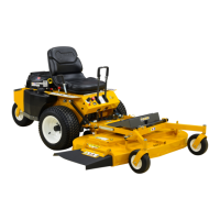
Coupler Ring in
Locked Position
PTO Drive
Shaft
PTO Coupler
U-Joint
Internal Balls
Locked on Shaft
Quick Disconnect Ring “Locked” Position
IMPORTANT: When installing the DS52 Mower
deck, make sure to retract the dolly wheel after
mounting the deck on the tractor.
6. Slide the deck the rest of the way on the deck
arms. If the deck is collection style (GHS
equipped model), the discharge chute will need
to be aligned and connected to the blower inlet
during the last 2 in. (51 mm) of slide action on
the support arms.
NOTE: Raising the mower body may be helpful
in tting and guiding the deck chute into the
blower.
7. Install the hitch pin through the hole on the end
of each support arm to lock the deck in place.
Two (2) hitch pins are included in the Owner’s
Packet of materials.
Hitch Pins Lock Deck
on Support Arms
Use Hitch Pins to Lock Deck on Support Arms