Assembly Instructions
21
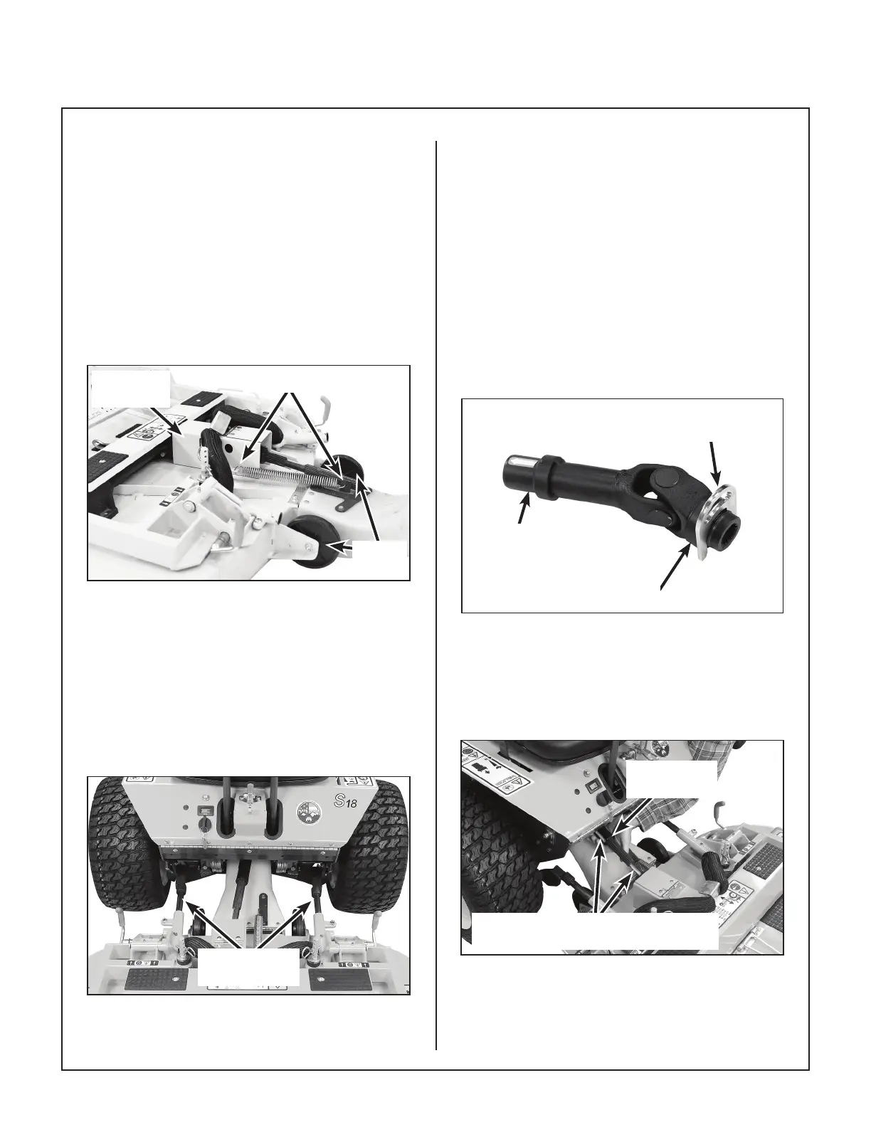
PTO Shaft Guard Installation
Position the shaft guard as shown and mount with
two (2) 1/4-20 x 1/2 in. bolts.
Tilt-Up Roller Wheel Installation
Mount the two (2) tilt-up roller wheels on the brack-
ets on the rear skirt of the deck housing using the
P/N 8490 axle bolt, 3/8 in. plain washer, 3/8 in. wave
spring washer (between bracket and wheel) and
3/8-16 in. Whiz locknut. Tighten the axle bolt until
the wheel rolls freely, but is not loose.
Attach Spring
Roller
Wheels
PTO Shaft
Guard
Tilt-Up Spring and Roller Wheel
Installation on Collection Deck
Mower Deck Installation on Tractor
Deck Installation
1. Lightly grease each deck support arm (2) on the
tractor. Refer to Mower Deck Installation
photo for location of deck support arm.
Deck Support
Arms
Mower Deck Installation
2. Engage the deck carrier frame tube sockets on
the tractor support arms. (Refer to Discharge
Chute and PTO Shaft Guard Installation
photo for socket location.) Slide the deck onto
the support arms approximately 3 in. (76 mm).
3. Retract the spring-loaded quick disconnect ring
on the PTO Coupler and insert the Coupler In-
stallation Tool (provided in Owner’s Packet) as
shown in the PTO Coupler Installation Tool
photo.
NOTE: The Coupler Installation Tool is provid-
ed for convenience, but is not required for in-
stallation.
PTO Coupler
Tube
Coupler
Installation Tool
Retract Spring-Loaded
Quick Disconnect Ring
PTO Coupler Installation Tool
4. Reaching under the tractor, slide the PTO cou-
pler tube onto the deck drive shaft (align arrow
decals), then install the coupler quick discon-
nect onto the tractor PTO drive shaft.
PTO
Connection
Arrows on Shaft and Tube
(Used to Align When Sliding Together)
PTO Shaft Connection