73
Maintenance Instructions ADJUSTMENTS
ADJUSTMENTS
Transmission Control
IMPORTANT: The proper adjustment of the trans-
mission control stops is essential for ecient op-
eration and life of the transaxle. These stops are
properly adjusted at the factory and should only re-
quire read justment if the transaxle or related
control linkage is removed or changed.
NOTE: It would not be unusual for a new machine,
after the initial 5 or 10 hours of operation, to begin to
not travel straight (this is due to the break-in of the
transmissions). To ne tune tracking, refer to Step 5 -
Straight Tracking Adjustment in this section.
Step 1 - Steering Lever Position Adjustment
NOTE: For proper operation, the steering levers
should be adjusted to sit evenly using the following
procedure.
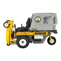
1. Examine the steering levers to make sure they
are parallel front to back in relation to one an-
other. If they are not equal, adjust accordingly.
(The handles may or may not be even at this
point.)
NOTE: The LH steering lever is non-adjust able.
This procedure will require adjustment of the RH le-
ver to make it even with the LH lever.
Levers should sit
parallel to each other
Lever Alignment
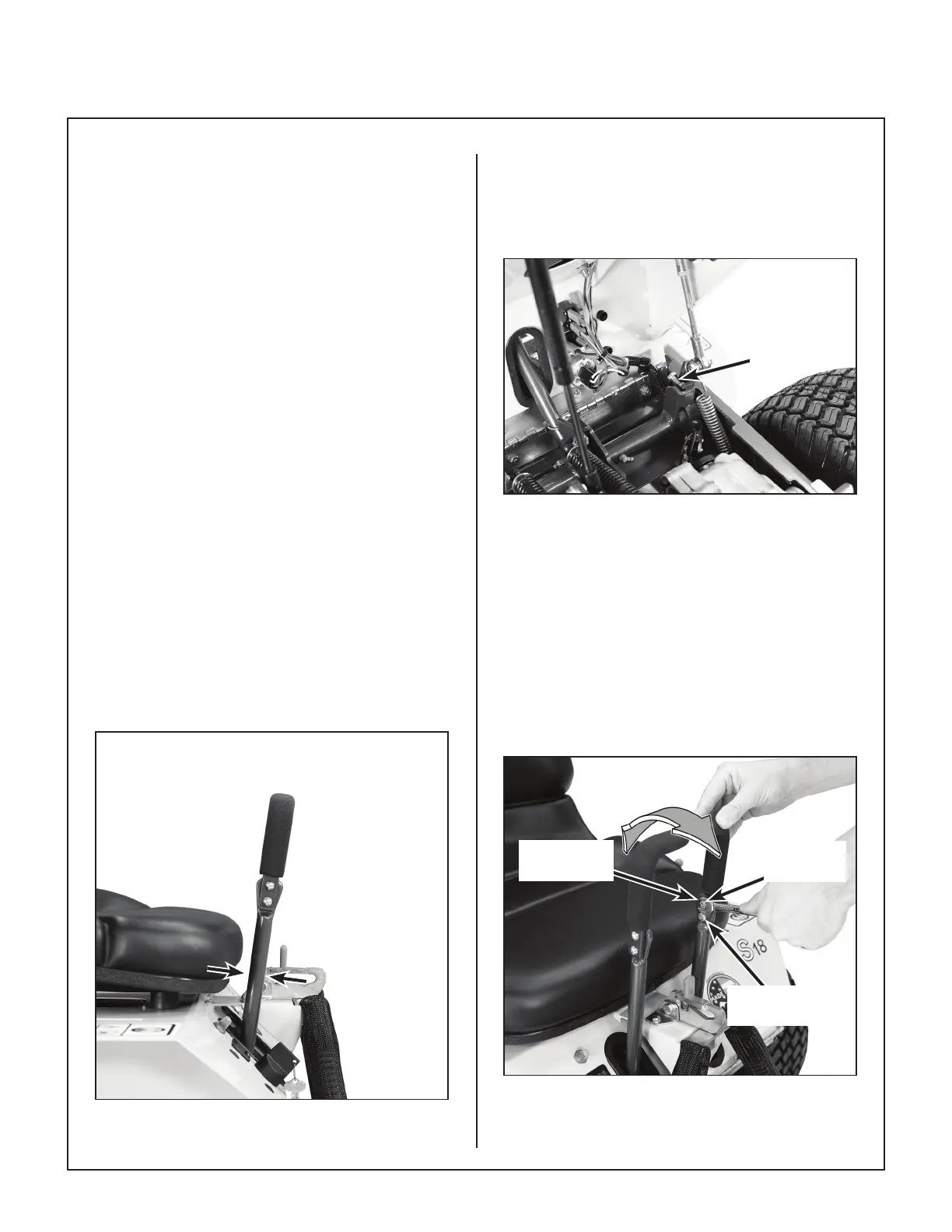
2. Adjust the position of the RH lever by turning the
stop bolt in the Speed Control Actuator in or out.
Turning the stop bolt in will make the RH lever
move back, and turning it out will make it move
forward. Tighten the locknut.
Stop
Bolt
Stop Bolt Location
Step 2 - Steering Handle Adjustment
1. An adjustment range of approximately 3 in.
(76 mm) is available on the steering handles–the
han dles can be adjusted forward or aft depend-
ing on the arm length of the operator. The han-
dles can be adjusted by loosening the locknut
at the pivot point and the locknut holding the
handle in position in the adjustment slide. Ad-
just han dles into most comfortable position and
tighten both locknuts.
Adjustment
Slide
Locknut
(Position)
Locknut
(Pivot Point)
Steering Handle Adjustment