79
Maintenance Instructions ADJUSTMENTS
Blade Brake Band Adjustment
The blade brake is designed to stop the blades with-
in ve (5) seconds after clutch disengagement. Ev-
ery 100 hours of operation verify correct perfor-
mance of the blade brake by following the procedure
in CHECKING/SERVICING the Blade Brake Ac-
tion in this section.
WARNING
It is important to check and maintain blade
brake action for safe operation of the ma-
chine.
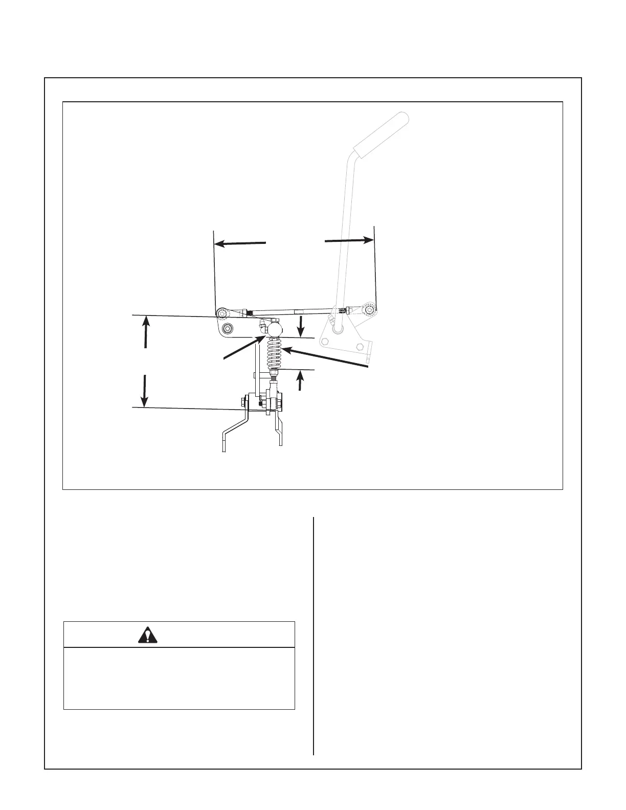
Adjust the working travel of the clutch idler pulley by
adjusting the brake band nut:
1. With the clutch disengaged, adjust the blade
brake band nut to achieve a 1/4 in. to 3/8 in.
(6.5 mm to 9.5 mm) gap between the PTO pul-
ley and clutch idler pulley as shown in the Blade
Brake Band Adjustment illustration.
NOTE: As the blade brake band/drum wears,
idler pulley travel will increase and it will be nec-
essary to adjust the brake band nut to maintain
the correct 1/4 in. to 3/8 in. (6.5 mm to 9.5 mm)
gap. If the gap is greater than this in the disen-
gaged position, the PTO belt may not declutch
adequately. Every 100 hours of operation
check the pulley gap and adjust if necessary.
PTO Clutch Disengaged
*NOTE: Factory preset dimensions. Reset to these
dimensions prior to adjustment if components have
been disassembled.
Clutch Spring Assembly
(Spring Uncompressed)
11 in.*
(280 mm)
6 in.*
(152.5 mm)
2-1/8 in.*
(54 mm)
Knuckle
Joint