Do you have a question about the wallas 2400 t and is the answer not in the manual?
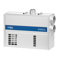
The main heating unit with pre-installed hoses and cables.
Includes mounting plate, bolts, base plate, and fastening screws for installation.
Contains hose binders, fuses, fuse box, and electrical connectors.
Includes control panel, extension collar, and fastening screws.
Installation, operation, and maintenance instructions manual.
Details on fuel, voltage, consumption, and heating power ratings.
Dimensions, weight, and maximum lengths for pipes and ducts.
Information on air openings, connections, and exhaust lead-throughs.
Explains forced air diesel heating, heat transfer, and air circulation.
Details the glow plug ignition, automatic control, and after-cooling process.
Notes that heaters are made from corrosion-resistant materials.
Covers country-specific rules, warranty validity, and intended marine use.
Advice on choosing a dry, protected, stable, and accessible location.
Notes on control panel placement, duct bending, and professional installation.
Guidance on protecting cables/hoses and creating drip loops.
Specifies space needs and avoiding hazardous areas.
Lists drills, jigsaw, and hole saws for creating installation openings.
Includes screwdrivers, pliers, crimpers, tape measure, and wrenches.
Details drill bit sizes and fastener types for mounting.
Highlights insulation for metal hulls and using original parts.
Fixing the mounting plate to a surface, ensuring horizontal position.
Lifting and locking the heater to the plate using mounting bolts.
Connecting the exhaust gas pipe to the heater using a hose clamp.
How to open and close the exhaust head (2460) using its mechanism.
Importance of sealing gasket surfaces with silicone for water tightness.
Steps for mounting exhaust head, spacing tube, and mounting plate with bolts.
Positioning the heater on the plate and securing it with bolts.
Ensuring the overheating cut-out reset button is accessible for operation.
Cutting installation hole in a dry, vertical surface, considering thermostat sensor.
Detailed measurements for the control panel installation cut-out.
Connecting the panel cable and using screws for installation.
Using the extension collar for surface mounting the control panel.
Looping the control panel cable and using a cable tie for strain relief.
General advice on leaving slack for cables and fuel lines for service.
Connecting accessories like remote control and timer to the control panel.
Using 12V DC, minimizing cable length, and selecting correct cross-sectional area.
Recommending a main switch on the positive cord and its proper usage.
Connecting power cord to battery terminals and installing a main fuse.
Requirements for 24V systems, including voltage reducer and 12V battery.
Emphasizes connecting the device to the boat's house battery.
Rules for making joints in power cords, including location and replacement.
Checking voltage during startup to ensure proper operation.
Standard hose lengths, lift height, and mandatory Wallas filter.
Adhering to local regulations for fuel hose material and inner diameter.
When fuel feed checks/adjustments are needed and by whom.
Mounting the fuel tank securely and close to the keel line.
Listing available Wallas fuel tank volumes with order codes.
Ensuring firm tightening to prevent air leaks and checking connection cleanliness.
Ensuring continuous fall for the black excess fuel return tube towards the tank.
Tank position relative to heater and vent tube height for safety.
Proper placement of the fuel tank filter to shield the pump from impurities.
Details for tank connector, suction tube, vent tube, filters, and clamps.
Models 2467 and 2460 suitability for 1800t/2400t exhaust pipes.
Ensuring free airflow, flat surface, and avoiding corners for lead-throughs.
Minimum distances from fuel filler, water surface, and transom placement.
Using lead-through as template, sealing cut-out, and goose neck requirement.
Preventing splash water entry and ensuring highest point is above water.
Awareness of hot exhaust gases, surroundings, and potential deck drying.
Requirement for drainage lock on exhaust tubes longer than 2 meters.
Using stainless steel pipe and heat-resistant silicone for connections.
Drilling a hole to prevent water accumulation in leaning exhaust installations.
Using insulation kits to prevent electrical circuits between hull and device.
Details of parts included for circular coaxial lead-throughs.
Installing in side or transom, always requiring a goose neck piece.
Spreading sealing agent on cut-outs and screw holes for water tightness.
Specific measurements for side lead-through and pipe length differences.
Lists components included with the side lead-through kit.
Procedure for removing the cap using a spring mechanism.
Ensuring correct part order and spring placement for proper closure.
Lubricating seals yearly with heat-resistant petroleum jelly.
Verifying the fitting is open before starting the device.
Lists components included with the closable lead-through kit.
Details for installing the closable deck lead-through 2460.
Pipe length difference between exhaust gas pipe and inlet pipe for stability.
Using lead-through elevation 2069 for demanding conditions.
Illustrates different boat installations for air ducting layout.
Advice on routing ducts for optimal airflow and heat distribution.
Planning duct routes and locating registers near heated areas.
Using 60mm ducts, Y-fittings, and securing connections with clamps.
Adjusting registers for flow and preventing overheating by managing flaps.
Placing the control panel in the largest heated area for efficiency.
Insulating long runs or less-heated areas to minimize temperature loss.
Recommended maximum lengths for ducts and impact of friction/temperature loss.
Need for minimum ventilation hole (100 cm²) in the installation space.
Removing the grill part and turning it for air flow direction control.
Cutting a hole, screwing the register body, and connecting the duct.
Ensuring at least one air outlet of the heater remains open at all times.
Ensuring sufficient air intake, ventilation, and exhaust outlet placement.
Installing the operating switch away from liquids and out of reach of children.
Keeping hoses clean, using Wallas parts, and ensuring correct return tube fall.
Using 12V DC, short cables, and a main fuse near the battery.
Choosing safe outlet locations, using swan-necks, and insulating for metal hulls.
Isolating ducts and keeping registers open for proper function.
Advice on potential multiple starts, checking for leaks, and initial burn-off.
Section for installer to confirm completed steps and sign.
How to start the heater, indicator lights, and combustion stabilization.
Steps for initial start-up if fuel line is empty.
How to turn off the heater using the heating switch.
Switching between thermostat and manual modes using the control knob.
How thermostat mode works, including sun-switch and conservation temperature.
Adjusting power manually and avoiding rapid knob movements.
Using air boost for moisture removal and adjusting air volume.
Activating fresh air ventilation and switching between min/max settings.
Shutting down the heater and the aftercooling process.
Using an accessory remote control and its operational limitations.
Meaning of yellow and green lights for heating and ventilation status.
Red light indicators for combustion status and aftercooling phase.
Orange lights indicating thermostat status, remote control, and sun-switch shutdown.
Recommends basic maintenance every 5 years by an authorized service shop.
Advice on occasional use, water removal, and winter storage.
Information on downloading the spare part catalogue.
Procedure for opening the device by removing the bottom plate.
Ensuring no wires or hoses are pinched during reassembly.
Noting that cables and hoses may need detachment for maintenance.
24-month warranty, extendable by 12 months via registration.
How to report defects, required proof, and authorized service options.
Exclusions like unauthorized modifications, improper use, wear parts, and accidents.
Validity for boat and cottage products, not vehicles or other areas.
Requirement to prove adherence to maintenance and safety instructions for claims.