K00114
- 74 -
ø 2 mm (
3
/
32
’’)
100 mm (3
15
/
16
’’)
65 mm (2
9
/
16
’’)
17,5 mm
(
11
/
16
’’)
4,5 mm (
11
/
64
’’)
47 mm (1
27
/
32
’’)
56,1 mm (2
13
/
64
’’)
10 12
17,5 mm
(
11
/
16
’’)
69 mm (2
23
/
32
’’)
104 mm (4
3
/
32
’’)
en
Installation
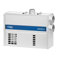
Control panel installation
Cut a suitable installation hole for the control panel in the selected location. Try to
install the panel in a vertical surface in a location that will remain dry.
Measurements of the control panel installation cut-out.
If necessary, predrill holes for the ø 2 mm (
3
/
32
”) screws.
You can utilize the sample of the box when drawing the lines of the
installation hole.
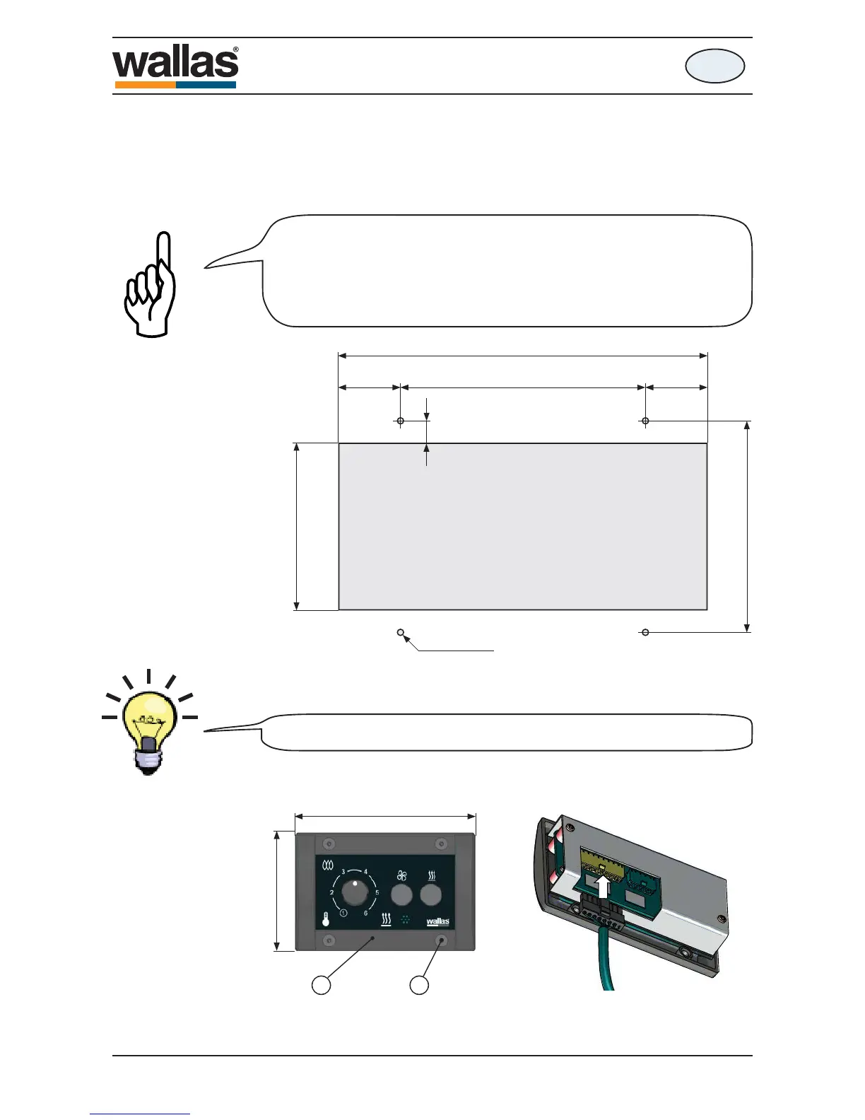
Connect the control panel cable from the device to the control panel (10).
Use the fastening screws to install the control panel to the installation cut-out (12).
The thermostat sensor is in the panel face, so select the location
with thermostatic operation/regulation in mind. Do not install close
to heat source or close to a window or door. Avoid locations that
might be contacted by direct sunlight. The length of the control
panel cable is 6 m.
1800 t / 2400 t
490535
 Loading...