Owner’s Manual 35
Wanco® Metro™ Message Sign
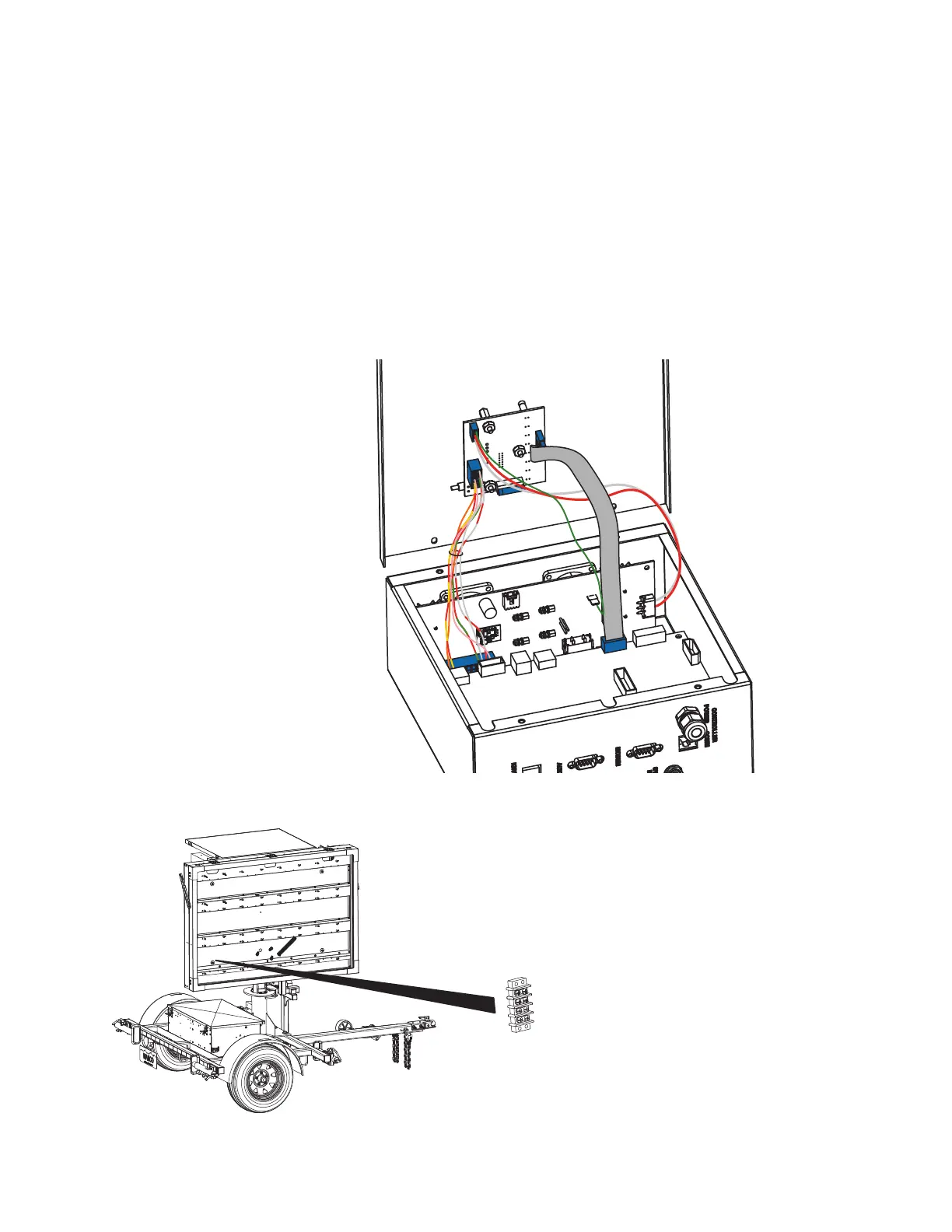
3. Check the radar power fuses and ground connection (see Figure 5-4). Replace the fuse
if necessary.
4. Check wiring connections at the radar terminal strip inside the display cabinet (see
Figure 5-5). Ensure they are proper, secure, and undamaged. Repair if necessary.
■ To access the radar terminal strip, remove the bottom left display module.
■ For instructions on removing a display module, see Section 6.2.3, page 39.
5. If all other steps failed to solve the problem, the radar head may have failed. Contact
the factory (see Section 1.4, page 2).
Figure 5-4. Radar wiring connections and fuses
Figure 5-5. Radar wiring terminals
➊ Computer box cover
➋ LED/status wiring
➌ Power/comm wiring
➍ Ground wiring
➎ System wiring
➏ Radar-power fuse
➐ Radar-power ground
➊
➋
➌
➍
➎
➏
➐