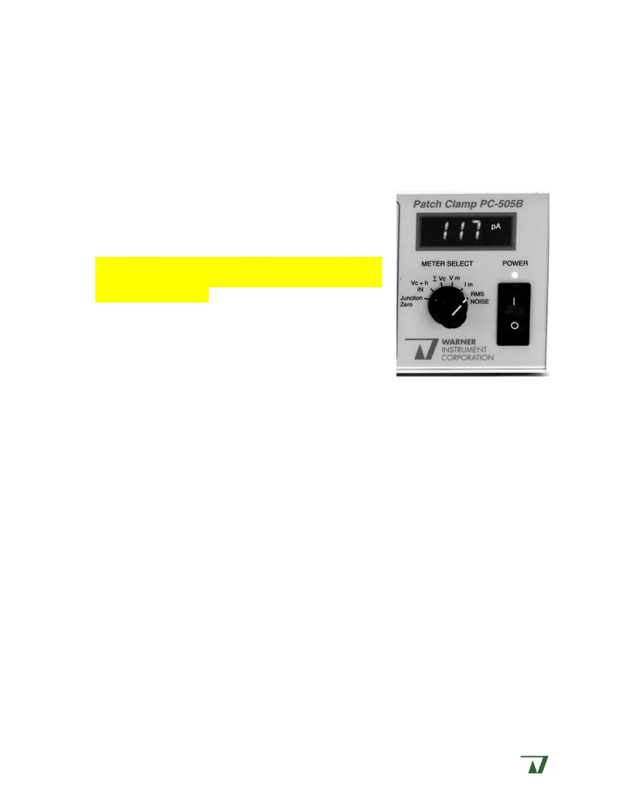
METER section
The six METER switch settings interact with other controls as noted. Due to the limiting
bandwidth of the meter display, any high frequency signals presented will be reported as its
DC time average value.
Junction Zero : This selection reports the voltage supplied by the JUNCTION ZERO control used
to compensate offset voltages present in the setup. Full scale reading is 120 mV.
V
c
+ h IN: This selection reports the sum of the COMMAND
IN voltage (V
c
; after attenuation by command sensitivity)
and the internal holding voltage (h). Full scale reading is
200 mV.
NOTE: To read h alone (in order to set the holding voltage
or holding current) turn COMMAND SENSITIVITY off or set the
external signal to zero.
V
c
: This selection reports the sum of all command
voltages. Mathematically, V
c
= (V
c
+ h IN) + (junction zero)
+ (auto zero) + (Series R). It does not include leak
subtraction. Full scale range is ±200 mV.
V
m
: This selection reports the transmembrane potential when in current clamp mode. Full
scale range is 200 mV.
I
m
: This selection reports the transmembrane current when in voltage clamp mode. Full
scale range is ± 1999 pA.
RMS noise: This selection reports the root mean square (RMS) value of the noise filtered to
a bandwidth of 1 kHz. This reading is valid only when the PROBE RESISTOR select is set to high
since the amplifier gain changes for other settings. The expected reading for the 50 G
resistor (with open input and properly shielded from 60 Hz interference) is approximately
0.040 pA. Full scale range is 1.999 pA RMS.
Front and rear panel BNC’s and connectors
The PC-505B has input and/or output BNC’s on both front and read panels. These
include I
m
and V
m
outputs, V
c
x10 and V
m
x10 outputs, GAIN and FILTER TELEGRAPHS, I
m
/V
m
mode telegraph, SYNC OUTPUT, and COMMAND INPUT.
Front and rear panel layouts are described below. With the exception of the rear panel
COMMAND IN BNC, all connector sleeves are connected to circuit ground and are insulated
from the chassis.
Front panel BNC’s
V
c
x10 – Output BNC reporting the sum of all voltages applied to the headstage input.