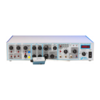
To establish a zero baseline reference potential, activate the junction zero circuit by
placing the AUTO-ZERO toggle switch into the on position. This turns the auto-zero LED on.
Next, depress and hold the AUTO-ZERO PUSHBUTTON to activate the automatic correction
circuit. The settling time is rapid when used with M pipette resistances, but can take
several seconds if used with G resistances. For complete compensation, keep the
pushbutton depressed until I
m
on the METER reads zero. If needed, small corrections to the
offset can be made by adjusting the JUNCTION ZERO control.
Releasing the AUTO-ZERO PUSHBUTTON locks the offset potential to the value set during
this operation. The value will remain in effect until the toggle is switched off or the
pushbutton is re-depressed. Switching the AUTO-ZERO toggle to off restores the
uncompensated current and voltage.
NOTE: Applied holding potentials remain active when the AUTO-ZERO toggle is turned on.
Depressing the AUTO-ZERO PUSHBUTTON, however, zeros all manual settings (including holding
potential, time-averaged test pulse, or command voltage) during the zeroing function.
Manual settings are re-applied when the PUSHBUTTON is released.
After zeroing the current, the magnitude of the junction potential can be read from the
meter (V
c
+h setting) or on the oscilloscope from the V
c
x10 output. The zero baseline setting
should remain stable so long as the AUTO-ZERO TOGGLE switch is set to on. If the value drifts,
then make sure the reference electrode is properly submerged. If the zero setting continues
to drift, then check your setup for errors (e.g., chloriding of the electrodes).
IMPORTANT! Once set, do not make further adjustments to the zero setting until you take a
new pipette. If you change the zero setting after forming a gigaseal, then you’ll not know the
true transmembrane potential!
Measure the pipette resistance (RP)
Measuring the resistance of the pipette is a routine method for determining the pipette's
condition before attempting to record data. Useful pipettes for patch recording can have
resistances within the range of 1-10 M and those for whole cell recording can range from
1-5 M. The specific resistance you’ll see is highly dependent on the solutions used and the
size of the tip. Generally speaking, smaller tips have higher resistance, more easily make
gigaseals, and are desired for patch work. Larger tips are better for whole cell work since it
is easier to rupture the membrane and the access resistance will be lower.
Pipettes with much higher resistance are likely to be blocked with debris from poorly
filtered pipette or bath solutions, or to have constricted tips from over-polishing. Those with
much lower resistance are probably broken. In either case, take a new pipette and start over.
The pipette resistance is measured with the pipette in the bath and a TEST PULSE applied.
A test pulse function can be driven from software (e.g., pClamp, PatchMaster) or from the
amplifier. In the amplifier, the test pulse is activated by setting the COMMAND SELECT toggle
to internal command, the SENSITIVITY SELECTOR toggle to x0.001, and the COMMAND SENSITIVITY
toggle to on. These settings activate and apply a line frequency, 1 mV peak-to-peak square