Do you have a question about the Warner PC-505B and is the answer not in the manual?
Defines terms, abbreviations, and signal polarity conventions.
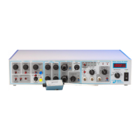
Details the controls on the instrument's front panel.
Precautions and steps for preparing the headstage for use.
Outlines the sequence of tests for instrument checkout.
Covers initial settings, voltage/current clamp, and bilayer recording steps.
Discusses electrode preparation, handling, and reference electrodes.
Lists specs, parts, warranty, and service information.
Explains manual formatting for clarity and consistency.
Lists and defines abbreviations for instrument controls and indicators.
Defines positive and negative conventions for membrane current and potential.
Describes the organization and purpose of front panel control blocks.
Explains the generation and use of the internal test pulse.
Details controls for setting zero baseline and compensating offsets.
Describes the ZAP function for membrane penetration.
Details controls for fast capacitance compensation.
Describes controls for whole cell recording compensation.
Explains compensation for series resistance and signal boost.
Explains compensation for leakage currents.
Details output modes and headstage resistor selection.
Explains the different clamp modes: voltage, zero current, and current.
Details gain selection and the 4-pole Bessel filter.
Explains the instrument's function as a potentiostat.
Describes the different meter readings for voltage, current, and noise.
Details the output BNC connectors on the front panel.
Describes rear panel BNC connectors and their signals.
Explains the gain telegraph signal and its settings.
Describes filter setting telegraph and synchronization output.
Details headstage connection, PSTAT, and SPEED TEST controls.
Discusses circuit and chassis ground connections for noise reduction.
Describes the headstage's function and lists different models.
Provides details on electrode holder types and usage.
Describes the model cell used for familiarization and troubleshooting.
Requirements for line voltage and instrument grounding.
Crucial safety precautions for handling the static-sensitive headstage.
Steps to prepare the headstage, including grounding and connections.
Lists tools and initial connections required for instrument checkout.
Specifies initial settings for front panel controls.
Specifies initial settings for oscilloscope parameters.
Procedures for checking RMS noise and Im output.
Procedures to verify Junction Zero and internal DC voltage commands.
Procedure to check external DC voltage commands.
Procedures to check internal AC voltage and Auto Zero controls.
Procedure to check Vc commands.
Procedure to check capacitance compensation controls.
Procedure to verify current clamp mode operation.
Lists initial settings for amplifier controls before operation.
Steps to mount and submerge the electrode tip in solution.
Procedure to establish a zero baseline reference potential.
Method for determining pipette resistance before recording.
Steps to attach to the cell and form a gigaseal.
Procedure for compensating electrode capacitance.
Method for measuring seal resistance (RS).
Compensating for membrane voltage errors due to leak.
Procedure for excising a membrane patch from the cell.
Procedure for performing cell-attached patch recordings.
Setting initial conditions and rupturing the membrane patch.
Compensating for series resistance using SERIES R and C-SLOW controls.
Optimizing amplifier performance using % correction.
Steps to switch the amplifier to current clamp mode.
Guidelines for recording in current clamp mode.
How external commands influence current capability.
Guidelines for performing bilayer recordings with the HB-205B headstage.
Explains methods for chloriding silver wire for electrodes.
Information on electrode holders and reference electrodes.
Guidelines for caring for, cleaning, and replacing parts of electrode holders.
Detailed explanation of reference electrodes and their use.
Lists detailed specifications for headstages, voltage/current clamp commands, and compensation.
Lists available accessories and replacement parts for the instrument.
Details the product warranty and service procedures.
Describes the signals available at front and rear panel outputs.
Specifies operating environment and physical dimensions.
Lists headstage models and electrode holder types with part numbers.
Details the product warranty coverage and limitations.
Provides notes on common service issues and procedures.
Declaration of conformity to EU directives for EMC.
Declaration of conformity to EU directives for LVD.
Statement on compliance with WEEE and RoHS directives.
Definitions for A/D converter, analog, and bandwidth.
Definitions for Bessel filter, BNC connector, capacitance, and compensation.
Definitions for CMD IN, command sensitivity, and command voltage.
Definitions for Faraday cage, gain, gain telegraph, and ground loop.
Definitions for headstage and Im (membrane current).
Definitions for junction potential, LED, mini-jack, and related terms.
Definitions for model cell, oscilloscope, output, signal polarity, and time constant.
Definitions for potentiometer, transient, transmembrane, and trim pot.
Definitions for TTL, unitary channel conductance, and Vm HOLD.
Definition for Vc.