B-1
B Installing the GC Column
The Agilent GC uses a capillary column, the inlet of which connects to the
front or back GC inlet port. The outlet connects to the heated transfer line,
which exits the oven at the bottom left-hand side.
See also: The Agilent GC user documentation.
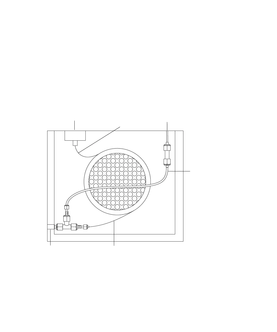
GC oven internal schematic:
A make-up gas is supplied coaxially to the capillary column via a T-piece
connected to the heated transfer line. An auxiliary EPC unit installed on the
Agilent GC supplies and controls the make-up gas. To maintain constant
make-up gas flow as the oven temperature changes, the make-up gas tube is
configured as an auxiliary GC column that operates in constant-flow mode.
The length of the make-up gas tube within the oven is critical, and only a
Waters engineer should install it.
GC inlet port Make-up gas supply
Heated transfer line
Capillary column
(inlet)
Capillary column (outlet)
Make-up gas tube