Watlow Series SD • 14 • Chapter 2 Install and Wire
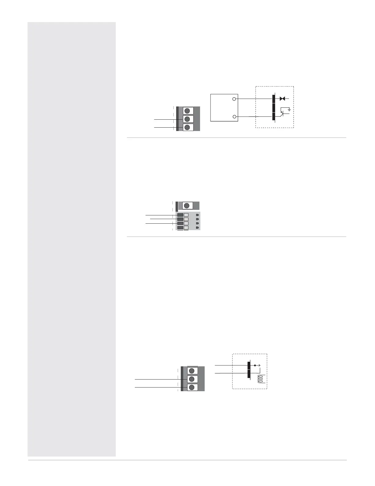
Figure 14a — Output 1 Switched DC
SD_ _ - _ C _ _ - _ _ _ _
• Supply current 30 mAÎ (dc) maximum.
• Supply voltage 6 to 12VÎ (dc).
• Not recommended for switching mechanical relays.
• Output supplies power.
4
56
5
6
dc+
dc-
Internal Circuitry
dc-
dc+
6 to 12VÎ (dc)
Load
Switched DC
-
+
5
6
Figure 14b — Output 1 Process
SD_ _ - _ F _ _ - _ _ _ _
• Analog output is scalable between 0 to 10VÎ (dc) or 0 to 20 mAÎ (dc).
• Load capability: voltage 1 k minimum; current 800 Ω maximum.
• Output supplies power.
• Cannot use voltage and current output at the same time.
4
8
5
6
7
volts+ 6
com- 7
amps+ 5
Figure 14c — Output 2 Mechanical Relay
SD_ _ - _ _ J _ - _ _ _ _
• Form A contact
• 2 A, resistive
• 125 VA pilot duty, 120/240VÅ (ac), inductive
• See Quencharc note.
• 240VÅ (ac) maximum.
• 30VÎ (dc) maximum.
• For use with ac or dc.
• Minimum load current 10 mA
• Output does not supply power.
2
3
4
3
4
normally open
common
Internal Circuitry
COM.
N.O.
Mechanical Relay
3
4
ç
Warning:
Use National Electric (NEC) or
other country-specific standard
wiring and safety practices when
wiring and connecting this con-
troller to a power source and to
electrical sensors or peripheral
devices. Failure to do so may
result in damage to equipment
and property, and/or injury or
loss of life.
Quencharc Note:
Switching pilot duty inductive
loads (relay coils, solenoids, etc.)
with the mechanical relay or solid-
state relay output options requires
use of an R.C. suppressor.
Watlow carries the R.C. suppres-
sor Quencharc brand name, which
is a trademark of ITW Paktron.
Watlow Part No. 0804-0147-0000.
Spring clamp wiring connector
note:
To insert the wire, push the wire
into the desired connection num-
ber, and it should automatically
lock into place. To remove the
wire, press and hold the orange
release tab with a small screw-
driver. Pull the wire out of the
connection. Solid or tinned wire
recommended.
Note: To prevent ground loops,
isolation needs to be maintained
from input to output when using
switched DC or analog process
outputs.

 Loading...


