Watlow Series SD • 17 • Chapter 2 Install and Wire
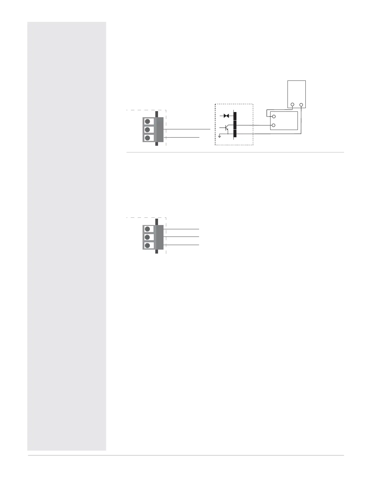
Figure 17a — Output 3 Open Collector
SD_ _ - _ _ _ C - _ _ _ _
• Maximum current sink 250 mAÎ (dc).
• Maximum supply voltage 42VÎ (dc).
• For inductive loads, see Quencharc note.
• Output does not supply power.
13 open collector
14 common
12
13
14
12 dc+
Internal Circuitry
dc-
COM.
dc+
42VÎ (dc) maximum
Open Collector
12
13
14
Load
-
+
Power
Supply
-
+
Class 2 power source
required for agency
compliance.
Figure 17b — Output 3 Process
SD_ _ - _ _ _ F - _ _ _ _
• Analog output scalable from 0 to 10VÎ (dc) or 0 to 20 mAÎ (dc).
• Load capability: voltage, 1 k
minimum; current, 800
maximum.
• Output supplies power.
• Cannot use voltage and current output at the same time.
12 amps +
13 volts +
14 com -
12
13
14
ç
Warning:
Use National Electric (NEC)
or other country-specific
standard wiring and safety
practices when wiring and
connecting this controller
to a power source and to
electrical sensors or periph-
eral devices. Failure to do
so may result in damage
to equipment and property,
and/or injury or loss of life.
Quencharc Note:
Switching pilot duty inductive
loads (relay coils, solenoids,
etc.) with the mechanical re-
lay or solid-state relay output
options requires use of an
R.C. suppressor.
Watlow carries the R.C. sup-
pressor Quencharc brand
name, which is a trademark
of ITW Paktron. Watlow Part
No. 0804-0147-0000.
Note: To prevent ground
loops, isolation needs to be
maintained from input to out-
put when using switched DC
or analog process outputs.

 Loading...


