Auto-Zone Plus Section 4
Start-Up and Troubleshooting 4-11
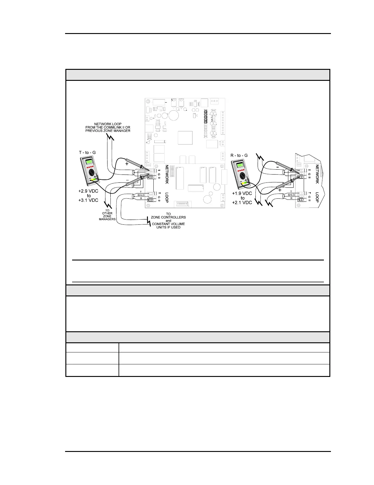
1.3.4 Checking the Zone Manager Network Loop
Diagram
Meter Set To Read DC Volts
The indicated readings are typical of a normally operating system. Actual readings may vary
slightly due to the number of units installed and other factors. Any significant deviation
from these values generally indicates a problem.
Note: These tests assume that the CommLink II is connected and powered, and that all
Zone Managers which are connected are also powered.
Overvie
Proper loop voltages are essential for reliable communications. It is normal to see
fluctuations on an operating communications loop. The average value should be close to the
acceptable range described below. Values will vary upon initial powerup for about 15-30
seconds as normal communications occur.
Measurements
LOCAL LOOP Acceptable Range
T - G (SHLD) 2.9 - 3.1 Volts DC
R - G (SHLD) 1.9 - 2.1 Volts DC